Experiment: resistance of a wire using Ohm’s law
Beyond NCERT In the JEE Main and NEET syllabus; the Class 12 book has no section for it.
Quick answer
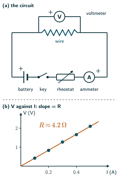
The Ohm’s law experiment finds the resistance of a wire from readings of the current through it and the potential difference across it. Connect the wire in series with a battery, key, rheostat and ammeter, put a voltmeter across the wire alone, and use the rheostat to take several pairs of V and I; the V–I graph is a straight line through the origin whose slope is R. Dividing R by the length gives the resistance per unit length, and with the diameter, the resistivity ρ = RA/l.
What is this experiment?
The principle behind it
By Ohm’s law the potential difference across a conductor is proportional to the current through it, V = RI (NCERT Eq. (3.3), page 83). So if you measure V across a wire for several currents I, the graph of V against I is a straight line through the origin, and its slope is the resistance R. The resistance also grows in step with the length:
Thus, doubling the length of a conductor doubles the resistance.
NCERT Physics Part I (Class 12), Section 3.4, page 84
The aim is to find the resistance of a given wire, and from it the resistance per unit length, by measuring the current through it and the potential difference across it.
Both the JEE Main 2027 and the NEET (UG) 2026 syllabuses list this under Unit 20, Experimental Skills: “The resistance of a given wire using Ohm’s law.” The NCERT textbook gives the law (Section 3.4, pages 83–85) but not the laboratory method, so this page describes the standard method.
Apparatus
- The wire under test (a resistance wire, a metre or so long), and a metre scale.
- A low-voltage laboratory battery or battery eliminator appropriate to the meters (for example 0–3 V), and a one-way key (plug key).
- A rheostat, a variable resistor used to change the current.
- An ammeter (for example 0–1 A) and a voltmeter (for example 0–3 V), each with a known least count.
- Connecting wires and a piece of sandpaper to clean their ends.
Voltmeter-ammeter circuit with a rheostat
- Connect the battery, the key, the rheostat, the ammeter and the wire in series, so that the ammeter measures the wire current plus the small voltmeter current; it approximates the wire current when the voltmeter resistance is much larger.
- Connect the voltmeter across the wire only, in parallel with it, so that it measures the potential difference between the wire’s ends.
- Join the + terminals of both meters towards the + terminal of the battery, so that the pointers move the right way.
- Use one fixed end and the sliding contact of the rheostat, initially at maximum resistance. The rheostat sets the current: sliding its contact changes the total resistance in the circuit and so the current through the wire.
- A good ammeter has a very small resistance and a good voltmeter a very large one, so that putting them in hardly changes the current or the potential difference being measured.
Procedure
- Clean the ends of the connecting wires and make all connections tight. Note the least count and the zero reading of each meter.
- Set the rheostat to maximum resistance before closing the key, then adjust it for a small current. Note the ammeter reading I and the voltmeter reading V.
- Move the rheostat contact to increase the current in steps, taking at least five pairs of readings of I and V.
- Open the key between readings, so that the wire does not heat up.
- Measure the length l of the wire between the points where the voltmeter is connected.
Resistance from the V-I graph
- For each pair of readings, R = V/I; the mean of these values is one estimate.
- Plot V (on the y-axis) against I (on the x-axis). If the wire obeys Ohm’s law the points lie on a straight line through the origin (from NCERT Eq. (3.3)).
- The slope of this line, ΔV/ΔI, is the resistance R. A slope read from the best straight line averages out the scatter of single readings.
- If I is plotted against V instead, the slope is 1/R.
- The resistance per unit length is R/l, in Ω m−1. Since R = ρl/A (NCERT Eq. (3.9), page 84), measuring the wire’s diameter with a screw gauge then gives its resistivity, ρ = RA/l.
Precautions and sources of error
- Keep the current small and pass it only while taking readings: a wire that heats up has a higher resistance, since the resistivity of a metal rises with temperature (NCERT Section 3.8, page 90).
- Read the meters straight on, to avoid parallax, and correct for any zero error (see systematic and random errors).
- The voltmeter itself draws a small current, so the ammeter reads slightly more than the current through the wire, and V/I comes out slightly low; with a voltmeter of very high resistance this error is small (reasoned from the circuit).
- Loose or dirty connections add resistance and make the readings unsteady.
- How big is the error? For a quotient the fractional errors add: ΔR/R = ΔV/V + ΔI/I. Since ρ = πd2R/(4l), Δρ/ρ = ΔR/R + 2Δd/d + Δl/l: the diameter counts twice (see combination of errors).
Solved examples
Example 1: Resistance from a set of readings
The readings are: I = 0.10, 0.20, 0.30, 0.40, 0.50 A and V = 0.42, 0.83, 1.27, 1.66, 2.10 V. Find the resistance.
Answer: V/I gives 4.20, 4.15, 4.23, 4.15 and 4.20 Ω, with a mean of about 4.19 Ω. The points lie close to a straight line through the origin. Take two points far apart on that line, not two of the readings: it passes through about (0.10 A, 0.42 V) and (0.50 A, 2.09 V), so its slope is (2.09 − 0.42)/
Example 2: Resistance per unit length
The wire in Example 1 is 0.80 m long. Find its resistance per unit length.
Answer: R/l = 4.19/0.80 ≈ 5.2 Ω m−1 (reasoned from NCERT Eq. (3.9), page 84, which makes R proportional to l).
Example 3: From resistance to resistivity
The same wire has a diameter of 0.40 mm. Find the resistivity of its material.
Answer: A = πr2 = 3.14 × (0.20 × 10−3)2 ≈ 1.26 × 10⁻⁷ m2. Then ρ = RA/l = 4.2 × 1.26 × 10−7/0.80 ≈ 6.6 × 10⁻⁷ Ω m (NCERT Eq. (3.9), page 84). This lies in NCERT’s range for metals, 10−8 to 10−6 Ω m (page 90).
Example 4: The voltmeter’s current
A voltmeter of resistance 4200 Ω is placed across a 4.2 Ω wire. What fraction of the ammeter’s current goes through the voltmeter?
Answer: the two are in parallel with the same potential difference, so the currents divide inversely as the resistances. The voltmeter takes about 4.2/(4200 + 4.2) ≈ 0.1 % of the current, so V/I comes out about 0.1 % low (reasoned from NCERT Eq. (3.3)).
Example 5: Which reading is more reliable?
Assume maximum reading uncertainties of ±0.01 A and ±0.01 V (not automatically equal to the least counts). Estimate the largest error in R from the first and the last readings of Example 1.
Answer: to first order, the maximum fractional uncertainty is ΔR/R ≈ ΔV/V + ΔI/I. First: 0.01/0.42 + 0.01/0.10 ≈ 2.4 % + 10 % ≈ 12 %. Last: 0.01/2.10 + 0.01/0.50 ≈ 0.5 % + 2.0 % ≈ 2.5 %. Large readings, near full scale, give a much better R. A screw gauge reading to 0.01 mm adds 2 × 0.01/0.40 = 5 % to ρ in Example 3.
Common mistakes to avoid
Common mistake
Connecting the voltmeter in series
The voltmeter goes across the wire, in parallel; the ammeter goes in series. A voltmeter in series would allow almost no current, because its resistance is very high.
Common mistake
Taking the slope of the I–V graph as R
If I is plotted against V, the slope is 1/R; only the V–I graph (V on the y-axis) has slope R (from NCERT Eq. (3.3)).
Common mistake
Leaving the current on for a long time
The wire heats, its resistivity rises, and R drifts upward during the readings (NCERT Section 3.8, page 90).
Quick revision summary
- Principle: Ohm’s law, V = RI; the V–I graph of an ohmic wire is a straight line through the origin.
- Circuit: battery, key, rheostat, ammeter and wire in series; voltmeter across the wire only.
- The rheostat varies the current; take at least five pairs of V and I.
- R = V/I for each pair, and R = slope of the V–I graph; resistance per unit length = R/l.
- With the diameter from a screw gauge, ρ = RA/l; keep the current small so the wire does not heat.
Formula sheet
- V = RI
- R = slope of the V–I graph = ΔV/ΔI
- resistance per unit length = R/l
- ρ = RA/l, with A = πr
- I–V graph: slope = 1/R
Questions students ask
Is finding a wire’s resistance by Ohm’s law the same as verifying Ohm’s law?
Yes, finding a wire’s resistance by Ohm’s law uses the same circuit and readings as verifying the law: if the V–I graph is a straight line through the origin, the wire obeys Ohm’s law, V ∝ I, at a steady temperature, and the line’s slope is its resistance (from NCERT Eq. (3.3), page 83). The NCERT Laboratory Manual Physics Class XII gives the aim as the resistance per unit length of a given wire from a graph of potential difference against current (Experiment 1), and Unit 20 of the JEE Main and NEET (UG) 2026 syllabuses lists “The resistance of a given wire using Ohm’s law.” The NCERT Class 12 textbook has no section on the method; it gives the law in Section 3.4 (pages 83–85).
Does it matter where the voltmeter is connected in the ammeter–voltmeter method?
Yes, where the voltmeter is connected decides which error enters V/I: across the wire alone, as on this page, V is right but the ammeter also counts the voltmeter’s small current, so V/I comes out slightly low; across the wire and the ammeter together, I is right but V includes the ammeter’s own drop, so V/I is R plus the ammeter’s resistance (beyond the NCERT text, reasoned from NCERT Eq. (3.3), page 83). For an 8.0 Ω wire, a 2000 Ω voltmeter across it gives about 7.97 Ω, 0.4 % low; across the wire and a 0.20 Ω ammeter it gives 8.20 Ω, 2.5 % high. So the first way suits resistances far below the voltmeter’s, the second far above the ammeter’s.
How can you find the resistance of a very short piece of wire by this method?
A very short piece of wire has so small a resistance that the voltmeter reading at a safe current is too small to read well, so measure a longer length of the same uniform wire and scale down, since resistance is proportional to length, R ∝ l (NCERT Eq. (3.5), page 84). If 1.20 m of the wire has 3.6 Ω, a 5.0 cm piece has 3.6 × 0.050/1.20 = 0.15 Ω. Measured on its own at 0.20 A, that piece would show only 0.030 V, so a voltmeter reading to 0.01 V would carry an error of about 33 %.
Why is a metre bridge more accurate than the ammeter–voltmeter method?
A metre bridge can be more accurate because it is a null method: at balance no current flows through the galvanometer, so the result depends only on a known resistance and two lengths of bridge wire, not on any meter’s calibration or on the current a meter draws. In the ammeter–voltmeter method the errors of both readings add in V/I, and the voltmeter itself draws a little current. Its accuracy still depends on the standard resistance, wire uniformity, contacts and length readings; it has errors of its own, from the resistance of its end strips and joins.
Practice questions
Try each question first, then open the answer to check your working.
-
Q1. Why is a rheostat used in this experiment?
Show answerHide answer
To change the current through the wire in steps, so that several pairs of V and I can be taken.
-
Q2. A reading gives V = 1.50 V and I = 0.30 A. What is the resistance?
Show answerHide answer
R = V/I = 1.50/0.30 = 5.0 Ω (NCERT Eq. (3.3), page 83).
-
Q3. Why should the current be passed only while readings are being taken?
Show answerHide answer
Otherwise the wire heats up, its resistivity rises, and the measured resistance drifts upward (NCERT Section 3.8, page 90).