Experiment: identifying a diode, LED, resistor and capacitor
Beyond NCERT In the JEE Main and NEET syllabus; the Class 12 book has no section for it.
Quick answer
Isolate and discharge components before suitable multimeter tests: a resistor reads similarly both ways, a diode conducts mainly forward, and an LED may also glow if the test voltage is sufficient. A capacitor may show a charging transient; respect polarised-capacitor markings and verify the meter’s test polarity and voltage. Colour bands and package markings help identify parts, but a simple test does not prove full operating health.
What is this experiment?
The principle behind it
The four components can be distinguished by markings and suitable multimeter tests. The introductory two-direction test below is for isolated, discharged components; polarised capacitors must retain their marked polarity. A resistor conducts equally in both directions, as Ohm’s law expects. A diode conducts essentially one way, because:
The forward bias resistance is low as compared to the reverse bias resistance.
NCERT Physics Part II (Class 12), Section 14.6, page 337
An LED also conducts one way and gives out light while it conducts; a capacitor lets no steady current through, but it stores some charge (NCERT Laboratory Manual, Physics, Class 12, Activity 8, page 167). On a meter, the glow needs enough test voltage and current (reasoned).
The aim is to pick out a diode, an LED, a resistor and a capacitor from a mixed collection of such items.
Both the JEE Main 2027 and the NEET (UG) 2026 syllabuses list this under Unit 20, Experimental Skills, as item 18: “Identification of diode, LED, resistor, a capacitor from a mixed collection of such items” (JEE wording). The 2026–27 NCERT textbook does not describe the method: its Chapter 14, still the 2025–26 reprint, ends with rectifiers in Section 14.7. So this page follows the NCERT Laboratory Manual (Physics, Class 12), Activity 8 (pages 167–173), with its Activities 4 and 9 on the multimeter.
Apparatus and the multimeter
- A multimeter, and the mixed collection of components (Laboratory Manual, page 167). The Manual prefers an analog multimeter; with a digital one, read “deflection” as “reading” (page 169). A pointer shows a capacitor’s brief kick plainly; a digital display, updated a few times a second, can miss it (reasoned).
- A multimeter works as an ammeter, a voltmeter or an ohmmeter (Laboratory Manual, Activity 4, page 150). An analog multimeter shows its readings with a pointer moved by a microammeter (Wikipedia, “Multimeter”).
- In the resistance mode, a cell inside the multimeter is connected and drives a current through the component; the meter senses that current, with its dial marked in ohms (page 150). On an analog meter this scale is non-linear, with its zero at the extreme right (pages 151 and 153).
- Which lead is positive? For measuring voltage the red probe is used for positive and the black for negative (page 153). In the particular analog meter described by NCERT, resistance mode connects the black lead to the positive terminal of the internal cell and the red lead to the negative (Laboratory Manual, Activity 9, page 175). For that meter, a diode is forward biased when the black lead touches its p-side. Other meters can differ: establish the test polarity and voltage from the instrument manual.
- NCERT Laboratory Manual slip (pages 168, 176 and 178): elsewhere the Manual calls the red lead “positive” in resistance mode, and its Table A 9.1 (page 176) lists a junction as forward biased with the red lead on the p-side. That follows the socket labels (red + for voltage), not the cell inside, which page 175 puts on the black lead. On an unfamiliar meter, test a diode whose band you can see: when it conducts, the lead on the unbanded (p) end is the positive one (reasoned).
- Some digital multimeters have a diode-test setting, which shows the forward voltage drop of a conducting junction (Wikipedia, “Multimeter”). Which lead is positive on it is given in the meter’s manual.
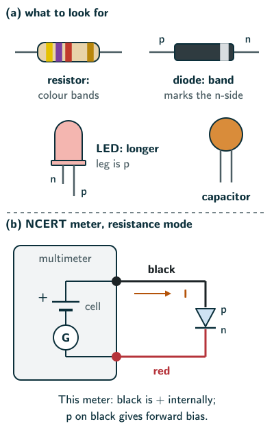
Testing each component with a multimeter
- Look first (Laboratory Manual, pages 167–169). Count the terminals: four or more, on a chip (a black rectangular block), mean an IC, though some ICs, such as the 7805, have only three (page 167); three terminals may mean a transistor, which the Manual confirms with the meter (page 168); two mean a resistor, a capacitor, a diode or an LED. Three colour bands followed by a silver or gold band mark a resistor (page 169). Outside the supplied collection many other two-terminal devices exist, so markings and part numbers are stronger evidence than terminal count alone (reasoned).
- Set the meter. The Manual uses resistance mode on the highest range (page 169): that range usually sends the smallest test current, and with a capacitor its larger resistance makes the kick last longer and easier to see (reasoned). Touch the metal ends of the two leads together and set the pointer to zero ohm with the zero-adjust knob (page 170). Beyond the Manual: when testing a diode, the test voltage must not exceed the diode’s maximum allowable voltage (NEETS Module 7, page 1-32). So find your meter’s test voltage in its manual, and if it has a low-voltage setting, such as diode-test mode, use it for diodes and LEDs (reasoned).
- Test both ways. Touch the leads to the two terminals of the component and watch the deflection; then repeat with the component terminals reversed (Laboratory Manual, page 169). Our safety advice (reasoned): first discharge a capacitor through a suitable resistor and confirm near-zero voltage; test a polarised (electrolytic) capacitor in its marked polarity only, with the meter’s positive lead (black, on the NCERT meter, page 175) on its + terminal, rather than reverse-biasing it to see a kick; and reverse an LED only when the meter’s test voltage is within the LED’s reverse rating (step 2).
- Watch for two more things: light from the component, and a deflection that appears for a moment and then dies away (pages 169–170).
- Record each component, marked with a letter, in two tables: one by the number of terminals, one by how it conducts (Tables A 8.1 and A 8.2, pages 169–170).
- Find the ends once you know what it is. A silver ring on a diode marks its n-side; on an LED the longer pin is usually the p-side (page 173). For the NCERT meter with black positive in ohms mode, the conducting orientation puts its p-side on black (page 175).
How each one responds
| Component | One way | Leads reversed |
|---|---|---|
| Resistor | steady reading | the same reading |
| Diode | deflects, no light | almost none |
| LED | may glow if test voltage is sufficient | little or none within its reverse rating |
| Non-polar capacitor | charging kick if large, then very high resistance | repeat only after discharge |
- Resistor: an equal deflection in both directions (Laboratory Manual, page 169). It obeys Ohm’s law, so the reading does not depend on which way the current flows.
- Diode: a deflection with no light one way, and no deflection the other (page 169). Its forward resistance is low and its reverse resistance high (NCERT page 337). Taking the two readings is the standard check of a diode: the larger value is the reverse resistance. A small signal diode has a reverse-to-forward ratio of several hundred to one; with adequate test voltage and good contact, two high readings suggest an open diode; two very low readings suggest a short (NEETS Module 7, page 1-32, US Navy, public domain).
- The “resistance” of a diode depends on the meter and the range. Ohmmeters differ in internal resistance and in the charge of their cells, so each sends a different current through the diode (NEETS Module 7, page 1-33). A diode is not ohmic, so V/I differs at each current. The displayed apparent resistance is therefore range-dependent; consult the meter’s test-current specification rather than assuming a universal range rule. A diode that passes this preliminary check can still fail in a circuit, because the meter works at a lower voltage, so the check is not conclusive (page 1-33).
- LED: a deflection with light one way, and much less or no deflection the other (page 169). The light is the difference from an ordinary diode. On a suitable low-current test setting the glow can be faint: shade the LED and look closely. An LED needs more forward voltage than a silicon diode, about 1.6–2.0 V for red and 2.5–3.7 V for blue (Wikipedia, “Light-emitting diode”), so a blue or white LED may not light from a meter’s 3 V cell (page 174; reasoned).
- Capacitor: no deflection either way, except that a large capacitor gives a momentary deflection; the Manual records it as an initial deflection that decays to zero (pages 169–170). A capacitor blocks a steady (dc) current (page 172). The meter’s cell charges it through the meter’s own resistance, and as the capacitor’s voltage rises the charging current, and the deflection, falls to zero (reasoned). It dies away over a few time constants, τ = RC, the same product as in a rectifier’s capacitor filter (see Example 4). A charged capacitor may show little initial kick on a repeat test. Discharge it through an appropriately rated resistor and confirm near-zero voltage before retesting; do not directly short an unknown charged capacitor.
Time constant of the charging kick (reasoned)
Precautions and sources of error
- Clean the leads of each component before measuring its resistance (Laboratory Manual, page 170).
- Check the zero: with the metal ends of the leads touching, the meter must read zero ohm; if not, set it with the zero-adjust knob, or the readings are unreliable (page 170).
- Do not touch the metal ends of the leads (the Manual says either of them, page 170): with a finger on each, your body’s resistance is in parallel with the component’s and changes the reading.
- Test out of circuit or with at least one lead disconnected, and never remove or insert a diode while voltage is applied (NEETS Module 7, page 1-32). Our safety advice (reasoned): turn circuit power off and verify it is off, and discharge capacitors through a suitable resistor and confirm near-zero voltage first.
- The Manual uses the highest resistance range (page 169). Our safety advice (reasoned): use a range whose test voltage and current suit the component (step 2); a digital capacitance range is better for identifying small capacitors.
Solved examples
Example 1: Sorting four unknowns
Four two-lead components are tested with a multimeter, each both ways. P reads 2.2 kΩ both ways. Q deflects one way, without light, and not at all the other way. R deflects and glows red one way and hardly deflects the other way. S gives a brief kick that dies away, both ways. Name each.
Answer: P is the resistor (equal both ways), Q the diode, R the LED and S the capacitor (Laboratory Manual, Activity 8, page 169).
Example 2: Is the diode good?
Three diodes are tested both ways. Diode 1 reads 800 Ω and 400 kΩ; diode 2 reads 12 Ω both ways; diode 3 shows no deflection either way. Assume the meter is suitable, the parts are isolated and the contacts are sound. Which passes this preliminary check?
Answer: Diode 1 passes the preliminary check: its reverse-to-forward ratio is 400 000/800 = 500, several hundred to one, as a good small signal diode should be. Diode 2 appears shorted (two low readings) and diode 3 appears open (two high readings); a complete functional test may still be needed (NEETS Module 7, page 1-32).
Example 3: Which end is p?
The NCERT-type analog multimeter, verified to put positive test voltage on black in resistance mode, deflects strongly when its black lead touches end X of a diode and its red lead touches end Y, and hardly at all when the leads are swapped. Which end is the p-side, and where should the band be?
Answer: For this specified meter, the black lead is the positive one in resistance mode (Laboratory Manual, page 175). The diode conducts when X is positive, so X is the p-side, and the band marking the n-side should be at Y (page 173).
Example 4: How long does the kick last?
On the range used, a multimeter’s internal resistance is taken as 20 kΩ. Estimate the time constant of the kick for a 470 μF capacitor and for a 0.1 μF capacitor.
Answer: 470 μF: τ = RC = 20 × 103 × 470 × 10−6 ≈ 9.4 s, so the pointer creeps back over several tens of seconds. 0.1 μF: τ = 20 × 103 × 0.1 × 10−6 = 2 ms, far too quick to see. This is why only a large capacitor shows a momentary deflection (reasoned; Laboratory Manual, page 169).
Example 5: Reading the colour code
A resistor has the bands yellow, violet, red and gold. Find its resistance and the range allowed by its tolerance. Is a meter reading of 4.6 kΩ acceptable?
Answer: Yellow 4, violet 7, and red gives the multiplier 102: R = 47 × 102 = 4700 Ω. Gold means ±5%, so 4465 Ω to 4935 Ω (colour code and tolerances from the Laboratory Manual, page 172). The reading of 4.6 kΩ lies in this range, so yes.
Common mistakes to avoid
Common mistake
Assuming the test polarity from probe colour alone
On the NCERT example analog multimeter the black lead is connected to the cell’s positive terminal in resistance mode (Laboratory Manual, page 175), so the diode conducts with its p-side on the black lead.
Common mistake
Testing only one way
One reading cannot tell a diode from a resistor: the Manual repeats every test with the component terminals reversed (Laboratory Manual, page 169). The one exception we advise is a polarised (electrolytic) capacitor: test it only in its marked polarity, positive lead on its + terminal (reasoned).
Common mistake
Missing the capacitor’s kick
A large capacitor’s deflection lasts only a moment and then falls to zero, so watch the pointer as the leads touch. A small one shows no deflection at all, just like an open (broken) part. Look at it too: a capacitor usually has its value printed on it, such as 0.1 or 102 (NCERT Laboratory Manual, Fig. A 8.1, page 168).
Common mistake
Holding both probe tips
Your body’s resistance in parallel with the component spoils the reading, especially for large resistances (Laboratory Manual, page 170).
Quick revision summary
- Resistance mode, highest range (the Manual’s choice): test each two-lead component both ways and watch for light and for a brief kick; isolate and discharge components first, and keep a polarised capacitor to its marked polarity (our safety advice).
- Resistor: the same reading both ways. Diode: low one way, very high the other, no light. LED: the same, and it may glow if the test supply is sufficient. Capacitor: no deflection either way; a large one gives a brief kick that dies away as it charges.
- NCERT’s example analog meter has black positive in resistance mode; verify an unfamiliar meter. A diode’s band marks its n-side; an LED’s longer leg is its p-side.
- A good small signal diode has a reverse-to-forward ratio of several hundred to one; two low readings suggest a short, and two high readings suggest an open only if the test voltage and contacts are adequate.
- Precautions: clean leads, check the zero, do not touch both probe tips, test out of the circuit.
Formula sheet
- colour code: R = (10a + b) × 10c, with a, b and c the first three bands
- tolerance: gold 5%, silver 10%, no fourth band 20%
- charging kick of a capacitor: τ = RC
- reverse-to-forward ratio = Rreverse/Rforward (also called the front-to-back ratio)
Questions students ask
Is identifying a diode, LED, resistor and capacitor in the JEE Main and NEET syllabus?
Yes, identifying a diode, an LED, a resistor and a capacitor is item 18 of Unit 20, Experimental Skills, in both syllabuses: the JEE Main syllabus lists “Identification of diode, LED, resistor, a capacitor from a mixed collection of such items”, and the NEET (UG) 2026 syllabus lists the same item. Unit 20 asks for “Familiarity with the basic approach and observations of the experiments and activities”. The NCERT textbook does not describe the method (its Chapter 14 is still the 2025–26 reprint); it is Activity 8 of the NCERT Laboratory Manual (Physics, Class 12), pages 167–173, which adds a transistor and an IC to the collection (page 167).
How do you check a diode with a digital multimeter?
A digital multimeter checks a diode best on its diode-test setting, beyond the NCERT text: this passes a small, limited current and shows the voltage across the junction instead of a resistance (Wikipedia, “Multimeter”). A typical small silicon diode shows roughly 0.5–0.8 V at the meter’s test current when its p-side is on the lead the meter makes positive, and an over-range reading with the leads reversed (0.7 V is not a universal upper limit); a red LED shows a larger drop and may glow faintly (reasoned). With suitable test voltage and sound contacts, near zero both ways suggests a short, and over-range both ways suggests an open; an LED may also read over-range because the meter cannot supply its forward voltage, as with an analog ohmmeter (US Navy, NEETS Module 7, page 1-32).
Can you test a capacitor with a digital multimeter?
Yes, a digital multimeter can test a capacitor in two ways, beyond the NCERT text: many have a capacitance range that reads the value directly, from a few picofarads up to some hundreds or thousands of microfarads (Wikipedia, “Multimeter”), and on a resistance range a large capacitor’s reading starts low and climbs to over-range as the meter’s current charges it (reasoned). Isolate it, discharge it through a suitable resistor and confirm near-zero voltage first; respect polarity on electrolytics; a reading that then stays low means it is shorted, and a capacitance well outside tolerance suggests a fault after confirming meter range and measurement conditions (reasoned). Ordinary multimeters seldom measure a capacitor’s leakage or equivalent series resistance, so one that shows the right value can still be faulty (Wikipedia).
How do you remember the resistor colour code?
The resistor colour code can be remembered by the NCERT Laboratory Manual’s (Physics, Class 12) term “BBROY GB VGW (B B ROY Great Britain Very Good Wife)”: black 0, brown 1, red 2, orange 3, yellow 4, green 5, blue 6, violet 7, grey 8 and white 9 (page 172). The Manual adds red (2%) and brown (1%) to the tolerance bands, beside gold (5%) and silver (10%), and notes that 2% and 1% resistors often have their values printed on them (page 172). So bands of blue, grey, orange and red mean 68 × 10 Ω = 68 kΩ ± 2%, anywhere from 66.64 kΩ to 69.36 kΩ (reasoned).
Practice questions
Try each question first, then open the answer to check your working.
-
Q1. Why is each component tested with the multimeter leads one way and then reversed?
Show answerHide answer
To see whether it conducts equally both ways, like a resistor, or in one direction only, like a diode or an LED (Laboratory Manual, page 169).
-
Q2. A two-lead component makes the pointer jump and then return to infinite resistance, whichever way the leads are connected. What is it?
Show answerHide answer
A capacitor: it charges through the meter, so the current flows only for a moment (Laboratory Manual, pages 169–170).
-
Q3. Why should you not hold the metal ends of both multimeter leads while measuring a resistance?
Show answerHide answer
Your body’s resistance is then connected in parallel with the component and changes the reading; the Manual says to avoid touching either metal end (Laboratory Manual, page 170).