Junction diode as a rectifier
NCERT Class 12 Physics Chapter 14 Section 14.7
Quick answer
A rectifier uses a diode’s one-way conduction to turn ac into a voltage of one direction. A half-wave rectifier, one diode in series with the load, passes only alternate half-cycles, so its output frequency equals the input’s, 50 Hz for 50 Hz mains; a full-wave rectifier with a centre-tap transformer uses two diodes in turn, giving 100 Hz. A capacitor across the load, with a large time constant τ = C RL, smooths the pulses into nearly steady dc.
With your textbook
NCERT Physics Part II (Class 12), Chapter 14 “Semiconductor Electronics: Materials, Devices and Simple Circuits”, Section 14.7 “Application of Junction Diode as a Rectifier”, pages 338–340.
Open the official NCERT chapter (PDF, 1.9 MB, ncert.nic.in) (opens in a new tab)
Checked against the 2025-26 reprint on .
What is a rectifier?
Rectifier
A rectifier is a circuit that turns an alternating voltage into one that acts in one direction only, using a diode’s property of conducting only when it is forward biased. In NCERT’s words:
This property is used to rectify alternating voltages and the circuit used for this purpose is called a rectifier.
NCERT Physics Part II (Class 12), Section 14.7, page 338
A half-wave rectifier passes only one half of each ac cycle; a full-wave rectifier uses both halves. A filter, usually a capacitor across the load, smooths the pulses into a nearly steady dc voltage (NCERT pages 338–339).
In plain words: mains electricity pushes current one way and then the other, fifty full cycles a second. A diode lets the pushes in one direction through and blocks the others. In a centre-tapped transformer circuit, two diodes taking turns catch both kinds of push and send them the same way through the load, and a capacitor fills in the dips between the pulses.
Half-wave rectifier
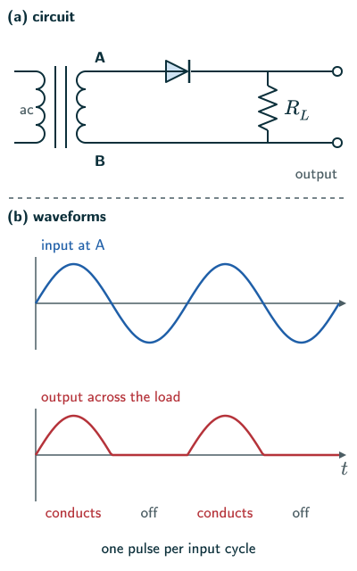
- When an alternating voltage is applied across a diode in series with a load, current flows only in the part of each cycle in which the diode is forward biased. So a pulsating voltage appears across the load only in those half-cycles (NCERT page 338, NCERT Figure 14.18).
- The secondary of a transformer supplies the desired ac voltage across the terminals A and B. When A is positive, the diode is forward biased and conducts; when A is negative, it is reverse biased and does not conduct (NCERT page 338).
- The reverse saturation current is negligible and can be taken as zero for practical purposes. But the diode’s reverse breakdown voltage must exceed the worst reverse voltage with a suitable margin. For this unfiltered half-wave circuit that is the secondary peak; adding a capacitor can raise it to nearly twice the peak, or the diode would break down in the negative half-cycles (NCERT page 338).
- So there is current through the load resistor RL, and an output voltage, in each positive half-cycle and none in the negative ones. The output still varies, but only in one direction: it is rectified. Because only half of each input cycle appears, this is a half-wave rectifier (NCERT page 338).
- The output has a dc component plus ripple. It has one pulse per input cycle, so its ripple repetition frequency equals the input frequency: 50 Hz for 50 Hz mains (NCERT Exercise 14.6, page 342; answer on page 352).
Half-wave output frequency (NCERT Exercise 14.6)
Full-wave rectifier with a centre-tap transformer
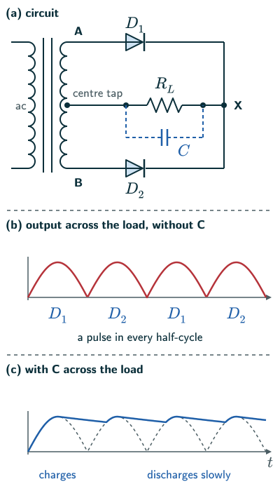
- A full-wave rectifier uses two diodes to give a rectified output from both the positive and the negative halves of the ac cycle (NCERT page 338, NCERT Figure 14.19(a)).
- The p-sides of the two diodes are connected to the two ends, A and B, of the transformer’s secondary, and their n-sides are joined together. The output is taken between this common point and the midpoint of the secondary, so the transformer has a centre tap (NCERT page 338).
- The voltage rectified by each diode is only half the total secondary voltage. Each diode works for half the cycle, and the two take alternate halves (NCERT page 338).
- When A is positive with respect to the centre tap, B, being out of phase, is negative: D1 is forward biased and conducts, while D2 is reverse biased and does not. When A becomes negative, B is positive, and D2 conducts instead. Either way the current through RL is in the same direction, so there is output in both halves of the cycle (NCERT page 339, NCERT Figure 14.19(b)–(c)).
- This is a more efficient circuit for getting a rectified voltage or current than the half-wave rectifier (NCERT page 339).
- It gives two pulses per input cycle, so the output frequency is twice the input frequency: 100 Hz for 50 Hz mains (NCERT Exercise 14.6, page 342; answer on page 352).
- Another full-wave circuit needs no centre tap but uses four diodes (NCERT page 338).
Full-wave output frequency (NCERT Exercise 14.6)
Capacitor filter
- The rectified voltage is a series of pulses shaped like half sine waves. It acts in one direction but does not have a steady value (NCERT page 339).
- To get a steady dc output, a capacitor is normally connected across the output terminals, in parallel with the load RL; an inductor in series with RL can serve the same purpose. Such circuits filter out most of the ac ripple, leaving a nearly steady dc voltage, so they are called filters (NCERT page 339).
- When the rectified voltage is above the capacitor’s voltage, the capacitor charges: from zero on the first pulse, then only near each peak. With ideal components and no load it would stay charged to the peak voltage; real diode drops, leakage and winding resistance modify this. With a load, it discharges through the load and its voltage falls, until the next pulse rises above its voltage and charges it to the peak again (NCERT page 339, NCERT Figure 14.20).
- How fast the voltage falls depends on the time constant, the product of C and the effective load resistance RL: the larger CRL, the slower the fall. To make it large, C must be large, so capacitor-input filters use large capacitors (NCERT page 339).
- NCERT wording (page 339): NCERT’s sentence reads as if the rate of fall of the voltage “is called the time constant”. The time constant is the product CRL; the rate of fall varies inversely with it.
- With a sufficiently light load and large capacitance, the output of a capacitor-input filter is close to the peak, less diode drops. Heavy loading gives larger ripple and a lower mean voltage. This type of filter is the most widely used in power supplies (NCERT page 339).
Time constant of the filter (NCERT page 339)
When choosing real parts, check reverse-voltage rating and the capacitor-charging surge current. In an ideal half-wave circuit with a capacitor already charged to Vm, the negative supply peak can place about 2Vm across the blocked diode. For a centre-tap circuit the corresponding peak reverse voltage is about twice the peak of each half winding.
Solved examples
Example 1: Output frequency (NCERT Exercise 14.6)
In half-wave rectification, what is the output frequency if the input frequency is 50 Hz? What is the output frequency of a full-wave rectifier for the same input?
Answer: Half-wave: one pulse per cycle, 50 Hz. Full-wave: two pulses per cycle, 100 Hz (NCERT Exercise 14.6, page 342; answer on page 352).
Example 2: Time constant and ripple
A full-wave rectifier on 50 Hz mains feeds a 1 kΩ load with a 1000 μF capacitor across it. Compare the time constant with the time between output pulses.
Answer: τ = CRL = 1000 × 10−6 × 1000 = 1 s. The pulses come every 1/100 s = 10 ms, a hundred times shorter, so the capacitor loses only a little charge between pulses and the ripple is small (beyond the NCERT text).
Example 3: Allowing for the diode
A half-wave rectifier uses a silicon diode, taken to drop about 0.7 V when conducting, on a secondary voltage of peak 10 V. Roughly what is the peak output?
Answer: About 10 − 0.7 = 9.3 V (threshold voltage from NCERT page 337; the rest beyond the NCERT text).
Example 4: Reverse voltage on a diode
In a centre-tap full-wave rectifier, each half of the secondary gives a peak of 12 V. What largest reverse voltage does the non-conducting diode face?
Answer: While D1 conducts, X is at about +12 V and B is at −12 V, both relative to the centre tap, so D2 faces about 24 V, the full secondary voltage. Its breakdown voltage must be well above this (reasoned from NCERT page 338).
Example 5: Ripple frequency
A full-wave rectifier with a capacitor filter works on 50 Hz mains. How often does the output voltage rise and fall?
Answer: The capacitor is recharged by each of the two pulses in every input cycle, so the ripple repeats every 10 ms: 100 Hz. With a half-wave rectifier it would be 50 Hz (reasoned from NCERT page 339 and NCERT Exercise 14.6).
Common mistakes to avoid
Common mistake
Thinking a rectifier gives steady dc by itself
Its output is a series of half-sine pulses in one direction; a filter, usually a large capacitor, is needed to smooth it (NCERT page 339).
Common mistake
Giving a full-wave rectifier the input frequency
It gives a pulse in every half-cycle, so its output frequency is twice the input: 100 Hz for 50 Hz mains (NCERT Exercise 14.6, page 342).
Common mistake
Connecting the filter capacitor in series with the load
The capacitor goes across the output, in parallel with RL; it is an inductor that would go in series (NCERT page 339).
Quick revision summary
- A diode conducts only in forward bias, so it can rectify ac.
- Half-wave: one diode in series with the load; output only in alternate half-cycles; output frequency f.
- Full-wave with a centre-tap transformer: two diodes conduct in turn; output in every half-cycle; output frequency 2f.
- A capacitor across the load smooths the pulses: it charges to the peak and discharges slowly through RL; a large time constant τ = CRL gives a small ripple.
Formula sheet
- fout = f (half-wave)
- fout = 2f (full-wave)
- τ = C RL
Questions students ask
What is the difference between a half-wave and a full-wave rectifier?
A half-wave rectifier uses one diode in series with the load and gives output only in the half-cycles in which it is forward biased, while NCERT’s full-wave rectifier uses two diodes and a centre-tap transformer, so the load current flows the same way in both halves of the cycle (NCERT pages 338–339). It gives two pulses per input cycle, not one, and NCERT calls it “a more efficient circuit” (page 339). Beyond the NCERT text, for the same peak its average (dc) output is twice as large and easier to smooth (US Navy, NEETS Module 7), and with ideal diodes, a resistive load and no filter its conventional rectification efficiency, power in the dc component over total input power, is 8/π ≈ 81.1% against 4/π ≈ 40.5% (Wikipedia, “Rectifier”).
What is the ripple factor of a half-wave and a full-wave rectifier?
The ripple factor of a rectifier, a quantity beyond the NCERT text, is the rms value of the ac part of its output divided by the dc (average) value: about 1.21 for half-wave and 0.48 for full-wave rectification, with ideal diodes, a resistive load and no filter. Both follow from γ = √[(Vrms/Vdc) − 1] (Wikipedia, “Ripple (electrical)”) with the output’s rms values, Vm/2 and Vm/√2, and dc values, Vm/π and 2Vm/π, for a peak output Vm (Wikipedia, “Rectifier”). A suitably sized capacitor filter brings it far lower. The ideal diode dissipates no power in this model: the quoted 40.5%/81.1% measure the useful dc component, not total energy lost as heat in the rectifier.
What is a bridge rectifier, and how is it different from a centre-tap full-wave rectifier?
A bridge rectifier is the four-diode full-wave rectifier without a centre tap that NCERT mentions on page 338: beyond the NCERT text, the ac goes across two opposite corners of a ring of four diodes and the load across the other two, so in each half-cycle two diodes conduct and drive current through the load the same way (US Navy, NEETS Module 7, Chapter 4). Using the same full secondary winding voltage, it gives nearly twice the peak output of the centre-tap arrangement at the same ripple frequency (NEETS), as each diode of a centre-tap circuit rectifies only half the secondary voltage (NCERT page 338). But its current passes through two diodes, so with silicon it loses twice the 0.7 V drop of one diode (reasoned from NCERT page 337).
How do you calculate the ripple voltage of a capacitor filter?
The ripple voltage of a capacitor filter, the peak-to-peak fall and rise of its output, is ΔV ≈ I/(frC), beyond the NCERT text, for a load current I, capacitance C and fr recharging pulses per second (Wikipedia, “Ripple (electrical)”). It holds when CRL is much longer than the gap between pulses: the capacitor then supplies a nearly steady current I for a time 1/fr, losing a charge I/fr, so its voltage falls by that charge divided by C (reasoned from Q = CV). So doubling C, halving the load current or going from half-wave to full-wave rectification each roughly halves the ripple.
Is the half-wave rectifier in the JEE Main and NEET syllabus?
Yes, the half-wave rectifier is in both syllabuses as part of “diode as a rectifier”, which Unit 19, Electronic Devices, of the JEE Main syllabus and of the NEET (UG) 2026 syllabus lists right after the diode’s I-V characteristics. NCERT Class 12 Physics Part II covers the half-wave rectifier, the centre-tap full-wave rectifier and the capacitor filter in Section 14.7 (pages 338–340) of the 2025–26 reprint. NCERT only notes in passing that a four-diode full-wave circuit exists and defines neither the ripple factor nor rectification efficiency, so questions on those go beyond the book.
Practice questions
Try each question first, then open the answer to check your working.
-
Q1. In a half-wave rectifier, why is there no output in the negative half-cycle?
Show answerHide answer
Then the diode is reverse biased and does not conduct; its reverse current is negligible (NCERT page 338).
-
Q2. In a centre-tap full-wave rectifier, why does the current through the load flow the same way in both halves of the cycle?
Show answerHide answer
In one half D1 conducts and in the other D2; both deliver current from the common n-side point X through RL to the centre tap (NCERT page 339).
-
Q3. Why do capacitor-input filters use large capacitors?
Show answerHide answer
A large C gives a large time constant CRL, so the capacitor voltage falls only slowly between pulses and stays near the peak (NCERT page 339).