Logic gates
Beyond NCERT In the JEE Main and NEET syllabus; the Class 12 book has no section for it.
Quick answer
A logic gate is a digital circuit whose inputs and output each take one of two states, 1 (HIGH) or 0 (LOW); its truth table lists the output for all 2n combinations of n inputs. An OR gate gives 1 if any input is 1 (Y = A + B), an AND gate only if all are 1 (Y = A·B), and a NOT gate inverts its one input. NAND and NOR are AND and OR followed by NOT, so NAND gives 0 only when all inputs are 1 and NOR gives 1 only when all are 0; either alone can build every other gate.
What is a logic gate?
Logic gate
A logic gate is a digital combinational circuit with one or more inputs and one output, in which each input and the output is in one of two states, 1 (HIGH) or 0 (LOW), and after its propagation delay the output follows a fixed rule of the valid input states. The US Navy’s public-domain Navy Electricity and Electronics Training Series (NEETS), Module 13, page 2-5, names them: “The devices that accomplish these operations are called logic gates, or more informally, gates.” They are the decision-making circuits of computers and other digital equipment (same page), and they are made from transistors, diodes and resistors, usually as integrated circuits (NEETS Module 13, page 3-38).
The 2026–27 NCERT textbook has no section on logic gates: its Chapter 14, still the 2025–26 reprint, ends with rectifiers in Section 14.7. The chapter opens with the devices such circuits are built from:
Devices in which a controlled flow of electrons can be obtained are the basic building blocks of all the electronic circuits.
NCERT Physics Part II (Class 12), Section 14.1, page 323
The JEE Main 2027 and NEET (UG) 2026 syllabuses list logic gates, OR, AND, NOT, NAND and NOR, in Unit 19. This page follows NEETS Module 13, Chapter 2.
In plain words: a logic gate answers a yes-or-no question about its inputs. An AND gate says “yes” only if every input says “yes”; an OR gate says “yes” if any input does; a NOT gate turns “yes” into “no” and “no” into “yes”. Wire enough of these together and you can build a calculator or a computer.
Truth tables
- A logic variable has two logic states, 1 and 0, which stand for TRUE and FALSE (NEETS Module 13, page 2-2). In a circuit they are two logic levels, HIGH and LOW. In positive logic, the one used on this page, the 1 state is the more positive voltage (page 2-3).
- A truth table lists every possible combination of the inputs with the output for each (page 2-5). With n inputs there are 2n combinations: 4 rows for two inputs, 8 for three (page 2-8):
Rows in a truth table with n inputs
- To be sure no row is missing, write the inputs in the order of counting in binary: 00, 01, 10, 11 for two inputs (reasoned).
- A gate’s rule can also be written as a Boolean expression. The plus sign means OR and is not addition; a dot, or two letters side by side, means AND; a bar over a letter or expression means NOT, its complement (NEETS Module 13, pages 2-2, 2-6 and 2-10). So in logic 1 + 1 = 1.
Real HIGH and LOW levels are voltage ranges, not universally 1 V and 0 V. A voltage between the specified input ranges is not a guaranteed logic state. For example, the TI SN7400 datasheet specifies LOW input at or below 0.8 V and HIGH at or above 2.0 V under its operating conditions. These thresholds are family-specific.
OR, AND and NOT gates
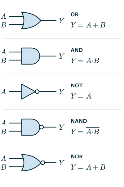
- OR gate, Y = A + B: the output is 1 if at least one input is 1, and 0 only when every input is 0 (NEETS Module 13, page 2-10). It works like two switches in parallel lighting a lamp: closing either switch lights it.
- AND gate, Y = A·B: the output is 1 only when all the inputs are 1 at the same time (page 2-6). It works like two switches in series: both must be closed.
- NOT gate (inverter), : one input, and the output is its opposite, 0 for 1 and 1 for 0 (page 2-12).
| A | B | OR | AND |
|---|---|---|---|
| 0 | 0 | 0 | 0 |
| 0 | 1 | 1 | 0 |
| 1 | 0 | 1 | 0 |
| 1 | 1 | 1 | 1 |
| A | NOT A |
|---|---|
| 0 | 1 |
| 1 | 0 |
OR, AND and NOT
- For 0 and 1, AND gives the same results as ordinary multiplication, while OR differs from addition only in 1 + 1 = 1 (reasoned from the tables).
NAND and NOR gates
- NAND gate, : an AND gate with a NOT gate at its output. Its output is 0 only when all the inputs are 1, and 1 when any input is 0 (NEETS Module 13, page 2-14).
- NOR gate, : an OR gate with a NOT gate at its output. Its output is 1 only when all the inputs are 0 (page 2-16).
| A | B | NAND | NOR |
|---|---|---|---|
| 0 | 0 | 1 | 1 |
| 0 | 1 | 1 | 0 |
| 1 | 0 | 1 | 0 |
| 1 | 1 | 0 | 0 |
NAND and NOR
- De Morgan’s theorem (NEETS Module 13, page 2-31) connects them with OR and AND. Each line can be checked by its truth table; Example 5 checks the second:
De Morgan’s theorem
- Universal gates: NAND gates alone, or NOR gates alone, can be combined to do the work of every other gate, so they are called universal logic gates (Wikipedia, “Logic gate”). The basic steps:
- NOT from NAND: join the two inputs, so both are A: the output is , which is (Wikipedia, “NAND logic”). In the same way a NOR gate with its inputs joined is a NOT gate (reasoned; extras Q5).
- AND from NAND: a NAND gate followed by a NAND gate used as NOT (Example 3).
- OR from NAND: make and with two NAND gates used as NOT, and feed them into a third NAND gate. By De Morgan’s theorem its output is A + B:
OR from NAND gates
- With NOR gates the steps mirror these: a NOR gate followed by a NOR gate used as NOT gives OR, and a NOR gate fed with and gives AND, by De Morgan’s theorem (Wikipedia, “NOR logic”):
AND from NOR gates
- In practice, gates come as integrated circuits; the standard 14-pin 7400 chip, for example, holds four independent two-input NAND gates (TI datasheet). The NCERT Laboratory Manual (Physics, Class 12), Project 5, designs an automatic traffic-signal system from logic gates and lists two NOT gates or a single IC 7400, and four NAND gates or a single IC 7400 (page 223): a NAND gate with its inputs joined works as a NOT gate. The project’s self-assessment asks you to design OR, AND and NOT gates from NAND gates (page 226).
Solved examples
Example 1: A three-input gate
How many rows has the truth table of a three-input AND gate? What do a three-input AND gate and a three-input OR gate give for A = 1, B = 0, C = 1?
Answer: 23 = 8 rows (NEETS Module 13, page 2-8). AND: 1·0·1 = 0, since one input is 0. OR: 1 + 0 + 1 = 1, since at least one input is 1.
Example 2: Name the gate
A two-input gate gives the outputs 1, 0, 0, 0 for the inputs 00, 01, 10, 11. Which gate is it? Which gate gives 0, 1, 1, 1?
Answer: The first is 1 only when both inputs are 0: a NOR gate. The second is 0 only when both inputs are 0: an OR gate (truth tables above).
Example 3: Two NAND gates
The inputs A and B go to a NAND gate, and its output goes to both inputs of a second NAND gate. Find the final output.
Answer: The first gate gives . The second, with both inputs X, gives , which is , and the bar over a bar cancels: Y = A·B. The pair is an AND gate: for 00, 01, 10, 11, X = 1, 1, 1, 0 and Y = 0, 0, 0, 1 (reasoned).
Example 4: Reading waveforms
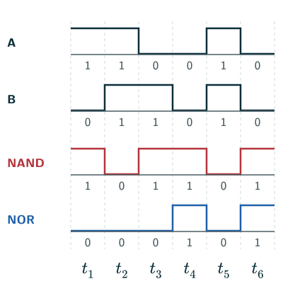
Ignoring propagation delays and treating the inputs as settled over six equal time intervals, input A is 1, 1, 0, 0, 1, 0 and input B is 0, 1, 1, 0, 1, 0. Find the output of a NAND gate and of a NOR gate in each interval.
Answer: NAND is 0 only when both inputs are 1 (intervals 2 and 5): 1, 0, 1, 1, 0, 1. NOR is 1 only when both inputs are 0 (intervals 4 and 6): 0, 0, 0, 1, 0, 1 (truth tables above; see the figure).
Example 5: Checking De Morgan’s theorem
Show that and have the same truth table.
Answer: For 00, 01, 10, 11: A + B = 0, 1, 1, 1, so = 1, 0, 0, 0. = 1, 1, 0, 0 and = 1, 0, 1, 0, so their AND is 1, 0, 0, 0. The columns agree in every row, so the two are equal (NEETS Module 13, page 2-31).
Common mistakes to avoid
Common mistake
Reading the plus sign as addition
In logic, A + B means A OR B, so 1 + 1 = 1, not 2 (NEETS Module 13, page 2-10).
Common mistake
Mixing up NAND and NOR
NAND gives 0 only when all inputs are 1; NOR gives 1 only when all inputs are 0. They agree for 0, 0 (both 1) and for 1, 1 (both 0), so test a mixed row: for 0, 1 NAND gives 1 and NOR gives 0.
Common mistake
Forcing every table onto the five gates
A combination of gates can give a table that is none of OR, AND, NOT, NAND and NOR. The outputs 0, 1, 1, 0 for 00, 01, 10, 11 (1 when exactly one input is 1) belong to the exclusive-OR (XOR) gate (NEETS Module 13, page 3-3). Work the combination out row by row before naming it.
Common mistake
Inverting the inputs instead of the output
A NAND gate inverts the output of AND, not its inputs. AND of the inverted inputs is a NOR gate, by De Morgan’s theorem.
Common mistake
Missing rows in a truth table
A gate with n inputs has 2n input combinations; writing them in binary counting order makes sure none is left out.
Quick revision summary
- Logic states 1 and 0 (HIGH and LOW in positive logic); a truth table lists the output for all 2n combinations of n inputs.
- OR: 1 if any input is 1. AND: 1 only if all inputs are 1. NOT: inverts its one input.
- NAND: AND then NOT, 0 only if all inputs are 1. NOR: OR then NOT, 1 only if all inputs are 0.
- NAND alone, or NOR alone, can make every other gate (universal gates); join the inputs to make a NOT gate.
- De Morgan’s theorem: NOT of an AND is the OR of the NOTs, and NOT of an OR is the AND of the NOTs.
Formula sheet
- OR: Y = A + B
- AND: Y = A·B
- NOT: Y = NOT A
- NAND: Y = NOT (A·B)
- NOR: Y = NOT (A + B)
- rows in a truth table: N = 2n
- NOT (A·B) = (NOT A) + (NOT B)
- NOT (A + B) = (NOT A)·(NOT B)
Questions students ask
Are logic gates in the JEE Main and NEET syllabus, and are they in NCERT?
Yes, logic gates are in both syllabuses: Unit 19, Electronic Devices, of the JEE Main syllabus and of the NEET (UG) 2026 syllabus ends with “Logic gates (OR. AND. NOT. NAND and NOR).”, printed the same way in both. They are not in the current NCERT Class 12 Physics Part II, however: its Chapter 14, still the 2025–26 reprint, ends with rectifiers in Section 14.7 and does not mention logic gates or Boolean algebra. The NCERT Laboratory Manual (Physics, Class 12) does use them, in Project 5, which designs an automatic traffic-signal system from logic gates (page 223).
What is the difference between basic gates and universal gates?
Basic gates are OR, AND and NOT, as the NCERT Laboratory Manual (Physics, Class 12) calls them (page 226); beyond the NCERT text, together they can implement any Boolean combinational function, while the universal gates, NAND and NOR, can each build every other gate on its own (Wikipedia, “Functional completeness”). AND and OR alone are never universal: raising an input from 0 to 1 never lowers their output, so no combination of them gives NOT, whereas NAND and NOR carry the inversion inside. Among single two-input Boolean operations, NAND and NOR are the individually universal ones. Feedback and storage introduce sequential-circuit behaviour, which needs more than a truth table of current inputs alone.
How many NAND gates are needed to make NOT, AND, OR, NOR and XOR gates?
Making gates from two-input NAND gates alone takes, beyond the NCERT text, one NAND gate for NOT, two for AND, three for OR, four for NOR and four for XOR (Wikipedia, “NAND logic”). NOR is the three-gate OR followed by a fourth NAND gate used as NOT; XOR feeds A and B into one NAND gate, then that output with A and with B into two more, whose outputs a fourth NAND gate combines. With NOR gates the roles swap: one for NOT, two for OR, three for AND and four for NAND (Wikipedia, “NOR logic”).
How are logic gates made from diodes and transistors?
Logic gates are made, beyond the NCERT text, from diodes or transistors switched by the inputs, and integrated circuits of MOSFETs are now the usual kind (Wikipedia, “Logic gate”). In a diode OR gate each input feeds a diode to one output tied to earth through a resistor, so any HIGH input forward biases its diode and pulls the output HIGH; reversed diodes and a resistor to the supply make an AND gate (Wikipedia, “Diode logic”). In conventional electronic logic, inversion and restoration of usable output levels require active devices, so logic families add transistors: resistor–, diode– and transistor–transistor logic (RTL, DTL, TTL) and CMOS (NEETS Module 13, pages 3-39 to 3-40).
How is De Morgan’s theorem used with logic gates?
De Morgan’s theorem is used with logic gates to swap AND for OR by inverting the inputs and the output, beyond the NCERT text: a NAND gate gives the same output as an OR gate with both inputs inverted, one of the equivalent pairs that the US Navy’s NEETS Module 13 tabulates (pages 2-21 to 2-22). That is how a circuit of AND and OR gates is rebuilt from NAND gates alone: Y = A·B + C·D equals NOT [NOT (A·B)·NOT (C·D)], two NAND gates feeding a third (reasoned). The theorem holds for any number of inputs, as in NOT (A·B·C) = (NOT A) + (NOT B) + (NOT C); the same law for sets is on the complement of a set page.
How many logic gates are there?
Seven familiar gate types are commonly named in digital electronics, beyond the NCERT text: NOT, OR, AND, NOR, NAND, XOR and XNOR (Wikipedia, “Logic gate”). This is not an exhaustive count of possible Boolean functions. The JEE Main and NEET (UG) 2026 syllabuses list five of them, OR, AND, NOT, NAND and NOR; of the other two, a two-input XOR gate gives a HIGH output when one and only one input is HIGH, and a two-input XNOR gate when both inputs are LOW or both are HIGH (US Navy, NEETS Module 13, glossary, second page).
Practice questions
Try each question first, then open the answer to check your working.
-
Q1. How many rows has the truth table of a four-input NAND gate, and in how many of them is the output 0?
Show answerHide answer
24 = 16 rows. The output is 0 in only one of them, when all four inputs are 1.
-
Q2. For A = 1 and B = 0, give the outputs of the OR, AND, NAND and NOR gates.
Show answerHide answer
OR 1, AND 0, NAND 1, NOR 0.
-
Q3. A three-input gate gives an output of 1 only when all three inputs are 0. Name it, and give its output for A = 0, B = 1, C = 0.
Show answerHide answer
A NOR gate (NEETS Module 13, page 2-16). One input is 1, so the output is 0.