Experiment: Young’s modulus of a wire
Beyond NCERT In the JEE Main and NEET syllabus; the Class 11 book has no section for it.
Quick answer
Young’s modulus of a wire is found by adding known loads M above a fixed preload on a long, thin wire and measuring its extension l with a micrometer, relative to a second reference wire on the same support (Searle’s apparatus). Then Y = MgL/(πrl), where L is the wire’s length and r its radius, or, from the slope of the extension-load graph, Y = gL/(πr × slope). The diameter usually causes the largest error because it enters squared, so it is measured many times with a screw gauge.
What is this experiment?
The principle behind it, in NCERT’s words
The ratio of tensile (or compressive) stress (σ) to the longitudinal strain (ε) is defined as Young’s modulus and is denoted by the symbol Y.
NCERT Physics Part II (Class 11), Section 8.5.1, page 170
(ΔL, the extension, is written l below.)
The aim is to find Young’s modulus of the material of a metal wire. A long, thin wire is hung from a rigid support and stretched by known loads; its length, its diameter and its extension under each load are measured, and Y follows from the formula above.
Both the NEET (UG) 2026 and the JEE Main 2027 syllabuses list this under Unit 20, Experimental Skills: “Young’s modulus of elasticity of the material of a metallic wire.” The NCERT textbook gives the theory (Section 8.5.1; see Young’s modulus) but not the method, so this page follows the method in NCERT’s Class XI Physics Laboratory Manual, Experiment 9 (pages 78–82), using Searle’s apparatus.
Apparatus
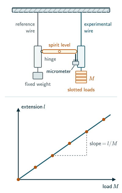
- Searle’s apparatus: two identical long wires of the same material hanging side by side from one rigid support. The reference wire carries a fixed weight that keeps it taut. The experimental wire carries a hanger for loads.
- Two frames, one hanging from the lower end of each wire, linked so that they can slide up and down past each other but cannot twist. A spirit level is hinged at one end to the reference frame; its other end rests on the tip of a vertical micrometer screw in the experimental frame. When the wire stretches, the level tilts; the screw is turned until the bubble is central again, and it moves through the extension. Its least count is the pitch divided by the number of circular-scale divisions, usually 0.01 mm.
- Slotted masses (for example 0.5 kg or 1 kg each) and the hanger.
- A screw gauge to measure the diameter of the wire (its zero error must be noted and allowed for), and a metre scale to measure its length.
Theory
Let M be the mass added above a fixed preload and l the extra extension from that preloaded reference reading. In equilibrium the increase in tension is Mg (see equilibrium of a particle). For a wire of original length L and radius r, the stress is Mg/(πr) and the strain is l/L, where l is the extension. So
Young’s modulus from one reading
Within the proportional limit the extension is proportional to the load (Hooke’s law), so a graph of l against M is a straight line through the origin with slope s = Δl/ΔM in metres per kilogram. The ratio l/M is usable when the reference-subtracted line passes through the origin. Using the slope instead of a single reading averages out the scatter:
Young’s modulus from the graph
Why a reference wire? For matched wires at the same temperature, thermal length changes are nearly equal. Any common vertical motion of their support also largely cancels because the micrometer measures the experimental wire relative to the reference wire. Unequal wire temperatures or unequal movement at the two suspension points leave residual error.
Why a long, thin wire? The extension l = MgL/(πrY) is proportional to L/r. A long, thin wire gives an extension large enough to measure accurately (Example 3).
Procedure
- Hang a small load on the experimental wire to remove kinks, and keep it there throughout; it is not counted in M.
- Measure the length L of the experimental wire, from the support to the point where it enters the frame, with a metre scale.
- Measure the diameter of the wire with the screw gauge at several places along it, in two perpendicular directions at each place, and take the mean. Halve it to get r.
- Adjust the micrometer screw until the bubble of the spirit level is exactly central, and note the micrometer reading.
- Add one slotted mass. Wait about a minute for the wire to settle, re-level the bubble with the micrometer and note the reading. The change is the extension for that load.
- Repeat, adding masses one at a time up to a safe maximum, within the straight, proportional range of the wire.
- Remove the masses one at a time, taking readings again. The loading and unloading readings for each load should agree. Take their mean for each load; subtracting the zero-load reading gives the extension l.
- Plot l against M, draw the best straight line through the points (it should pass through, or very near, the origin) and find its slope. (If you plot M against l instead, the slope is M/l and Y = gL × slope/(πr).)
A typical observation table (the data of Example 1). The micrometer readings are in mm, taken while adding loads (“load”) and while removing them (“unload”); the zero-load reading is 5.00 mm, and l is the mean reading minus 5.00 mm.
| M (kg) | Load | Unload | l (mm) |
|---|---|---|---|
| 0 | 5.00 | 5.00 | 0 |
| 1 | 5.20 | 5.20 | 0.20 |
| 2 | 5.38 | 5.40 | 0.39 |
| 3 | 5.59 | 5.59 | 0.59 |
| 4 | 5.78 | 5.78 | 0.78 |
| 5 | 5.98 | 5.98 | 0.98 |
Precautions. Use a wire without kinks. Add and remove loads gently, without jerks. Keep the total load within the proportional range and below the elastic limit, so that the wire returns to its original length. Measure the diameter carefully, because it enters the formula squared. Avoid backlash error: always make the final approach to the level position by turning the screw in the same direction.
Solved examples
Example 1: Young’s modulus from a set of readings
A steel wire of length 2.000 m and mean diameter 0.80 mm gives these mean extensions: 0 for 0 kg, 0.20 mm for 1 kg, 0.39 mm for 2 kg, 0.59 mm for 3 kg, 0.78 mm for 4 kg and 0.98 mm for 5 kg. Find Young’s modulus. Take g = 9.8 m s.
The points lie close to a straight line through the origin. A graph estimate using widely separated points (0, 0) and (5 kg, 0.98 mm) gives 0.196 mm per kg; a least-squares fit through the origin gives about 0.1958 mm per kg. Use 1.96 × 10 m kg here.
With r = 0.40 mm, πr = π(0.40 × 10), about 5.03 × 10 m. Then Y = gL/(πr × slope) = 9.8 × 2.00/
Answer: about 2.0 × 10 N m, the value NCERT Table 8.1 gives for steel.
Example 2: First-order worst-case uncertainty
In Example 1, L = 2.000 m is measured to 1 mm, d = 0.80 mm to 0.01 mm, and the extension for 5 kg, 0.98 mm, to 0.01 mm. Treat these as bounds on the measured quantities, take g and the masses as exact, and estimate the first-order worst-case percentage uncertainty in Y from one reading. The stated 0.01 mm bound applies to the extension difference itself.
From Y = 4MgL/(πdl), the first-order worst-case fractional uncertainty bounds add, with the diameter’s error counted twice (each Δ now means the error in that measurement):
that is, 0.05% + 2 × 1.25% + 1.02%, about 3.6%.
Answer: approximately 3.6%, of which the diameter contributes 2.5%. This is a first-order bound, not an exact error or a standard-uncertainty estimate. If two independent reading bounds are supplied for the extension difference, add them for its worst-case bound. That is why the diameter is measured at many places with a screw gauge.
Example 3: Why the wire must be thin
For the steel wire of Example 1, how would the extension per kilogram change if the diameter were halved to 0.40 mm?
The extension is proportional to 1/r, so halving the diameter makes it 2 = 4 times larger: about 0.784 mm per kg instead of 0.196 mm per kg.
Answer: four times larger, so it can be read with a smaller percentage error. Y itself is unchanged; only the extension changes. (A thinner wire also reaches its elastic limit at a smaller load, so the loads must be reduced.)
Common mistakes to avoid
Common mistake
Using the diameter in place of the radius
The formula needs πr with r = d/2. Using d gives an area four times too large and a Y four times too small.
Common mistake
Forgetting to convert units
Extensions are read in millimetres and diameters in millimetres too; convert both to metres before using the formula.
Common mistake
Counting the initial weight as part of the load
The small weight hung first to straighten the wire is not part of M; only the loads added after the first micrometer reading count.
Common mistake
Loading beyond the elastic limit
If the wire is overloaded it takes a permanent set, the unloading readings no longer match the loading ones, and the graph is no longer straight.
Quick revision summary
- The experiment finds Young’s modulus of a wire from its length, its radius and its extension under known loads.
- Searle’s apparatus uses a reference wire to reduce common temperature and support-motion errors; a spirit level and micrometer measure the extension.
- Y = MgL/(πrl) for one reading, or gL/(πr × slope) from the straight-line graph of l against M.
- The diameter, measured with a screw gauge, usually causes the largest error because it enters squared; small extensions also have large percentage errors, so loads giving about 1 mm of extension, and the graph’s slope, are used.
- In short: Y = MgL/(πrl), or Y = gL/(πr × slope).
Formula sheet
- Y = MgL/(πrl)
- Y = gL/(πr × slope), slope = Δl/ΔM
- ΔY/Y ≈ ΔL/L + 2Δd/d + Δl/l (first-order worst-case bounds; M and g exact)
Questions students ask
Is Searle’s method in the JEE Main and NEET syllabus?
The Young’s modulus experiment is in both the JEE Main 2027 and the NEET (UG) 2026 syllabus, though Searle’s method is not named: Unit 20, Experimental Skills, lists “Young’s modulus of elasticity of the material of a metallic wire”, and Searle’s apparatus is the usual school-laboratory method for it. So learn the formula Y = MgL/(πrl), how Y follows from the slope of the extension-load graph, why a reference wire is used, and why the diameter’s error counts twice.
What other methods are used to measure Young’s modulus?
Besides stretching a wire in Searle’s apparatus, Young’s modulus can be found by bending a bar, from the speed of sound in a bar, or with a testing machine. In the bending method a bar of breadth b and depth d, resting on supports a distance l apart, is loaded at its centre by a weight W, and its sag, or depression, δ gives Y = Wl/(4bdδ) (beam formula). The speed of a sound pulse along a thin bar, v = √(Y/ρ), also gives Y (sound in a bar), and a testing machine gives it as the slope of the straight part of the stress-strain curve.
Is Searle’s method for Young’s modulus the same as Searle’s method for thermal conductivity?
Searle’s method for Young’s modulus and Searle’s method for thermal conductivity are two different experiments, both designed by the Cambridge physicist George Searle: one stretches a wire, the other measures how well a good conductor such as copper conducts heat. In the thermal-conductivity apparatus a thick, lagged metal bar is heated at one end and cooled at the other by water flowing through a coil; the temperature drop along the bar and the heat carried away by the water give the conductivity (see conduction). Only the Young’s modulus experiment is in the JEE Main and NEET experimental-skills lists.
Why might the extension-load graph not pass through the origin?
The extension-load graph of a wire may miss the origin because the zero-load reading was not a true starting point, most often because the wire was not fully straightened, so that the first loads pulled out kinks as well as stretching it. A fixed zero offset shifts all points without changing the slope. Kinks can instead distort the first part of the graph, so exclude those readings rather than assuming every point has the same offset; so draw the best straight line through the points, without forcing it through the origin, and find Y from its slope. If the points bend at larger loads, investigate loss of proportionality, slipping clamps or instrumental error; use only a verified straight region.
Practice questions
Try each question first, then open the answer to check your working. Take g = 9.8 m s.
-
Q1. In Searle’s apparatus, why are the extensions measured relative to a second, reference wire?
Show answerHide answer
Matched wires at the same temperature change length nearly equally, and common support displacement affects both. Relative readings largely cancel these common effects; unequal heating or suspension movement still causes error.
-
Q2. A wire 1.5 m long and 0.50 mm in diameter stretches by 0.75 mm under a load of 2.0 kg. Find Young’s modulus of its material.
Show answerHide answer
πr = π(0.25 × 10), about 1.96 × 10 m. Y = MgL/(πrl) = 2.0 × 9.8 × 1.5/(1.96 × 10 × 0.75 × 10), about 2.0 × 10 N m (steel).
-
Q3. The diameter is measured with an error of 1% and the extension with an error of 2%; other errors are negligible. Estimate the first-order worst-case percentage uncertainty in Y.
Show answerHide answer
Approximately 2 × 1% + 2% = 4%, because the diameter enters the formula squared.