AC voltage applied to an inductor
NCERT Class 12 Physics Chapter 7 Section 7.4
Quick answer
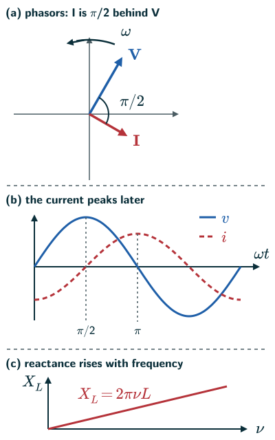
For an ideal linear inductor with zero dc current offset, when a sinusoidal voltage v = vm sin ωt is applied, the current is i = im sin(ωt − π/2): it lags the voltage by π/2, a quarter cycle. Its amplitude is im = vm/XL, where the inductive reactance XL = ωL = 2πνL is measured in ohm and grows with frequency. The average power supplied to the inductor over a cycle is zero.
With your textbook
NCERT Physics Part I (Class 12), Chapter 7 “Alternating Current”, Section 7.4 “AC Voltage Applied to an Inductor”, pages 181–183.
Open the official NCERT chapter (PDF, 2.4 MB, ncert.nic.in) (opens in a new tab)
Checked against the 2026-27 reprint on .
What happens when an ac voltage is applied to an inductor?
AC voltage applied to an inductor
An ac source v = vm sin ωt is joined to an inductor of inductance L and negligible resistance: a purely inductive circuit (NCERT Section 7.4, page 181). The current is then a quarter cycle behind the voltage, and its size is limited by the inductive reactance XL = ωL:
The inductive reactance is directly proportional to the inductance and to the frequency of the current.
NCERT Physics Part I (Class 12), Section 7.4, page 182
Over a full cycle the inductor takes no net energy from the source (NCERT page 183).
In plain words: an inductor fights changes in current. When the voltage is pushing hardest, the current is only just getting going; by the time the current reaches its peak, the voltage has already dropped to zero. The faster the current is made to swing back and forth, the harder the inductor fights, so its reactance grows with frequency.
Model used throughout: an ideal, lossless, linear inductor with constant L, driven sinusoidally at nonzero frequency. Current formulas, phasors and zero-current-at-voltage-peak examples refer to the zero-dc-offset solution. A real winding resistance lets an initial transient decay; no such decay is guaranteed for a perfect inductor.
Current lags the voltage by π/2
- Kirchhoff’s loop rule gives v − L di/dt = 0, the second term being the self-induced emf, with the minus sign from Lenz’s law (NCERT Eq. (7.10), pages 181–182). So di/dt = (vm/L) sin ωt (NCERT Eq. (7.11)).
- Integrating, i = −(vm/ωL) cos ωt + constant. NCERT selects the zero-offset sinusoidal solution by setting the constant to zero (page 182). Symmetry of the voltage alone does not force this: a perfect resistance-free inductor can retain a constant current fixed by its initial condition. The phase statement below describes the sinusoidal component. Using −cos ωt = sin(ωt − π/2) (NCERT Eq. (7.12), page 182):
Current in an inductor (NCERT Eq. 7.12)
- So the current lags the voltage by π/2, a quarter of a cycle. In the phasor diagram the current phasor I is π/2 behind the voltage phasor V as both rotate anticlockwise (NCERT page 182, Figure 7.6).
- The current reaches its maximum a quarter period, T/4 = π/(2ω), later than the voltage (NCERT page 183).
Inductive reactance
- The current amplitude is im = vm/(ωL). The quantity ωL plays the part of a resistance and is called the inductive reactance (NCERT Eqs. (7.13)–(7.14), page 182):
Inductive reactance (NCERT Eq. 7.13)
- With it, im = vm/XL; dividing both amplitudes by √2, the rms values obey I = V/XL too (as in NCERT Example 7.2). XL has the dimensions of resistance, and its SI unit is the ohm (NCERT page 182).
- XL is directly proportional to L and to the frequency (NCERT page 182). For a constant current, an ideal inductor has zero inductive voltage. However, a constant nonzero applied voltage produces a ramp, di/dt = V/L, not a finite steady current. In a real coil, winding resistance limits the eventual dc current (reasoned from NCERT Eq. (7.10)).
Zero average power in an inductor
- The instantaneous power supplied to the inductor is pL = iv = −imvm sin ωt cos ωt = −(imvm/2) sin 2ωt (NCERT page 183).
- Since sin 2ωt averages to zero over a cycle, the average power supplied to an inductor over one complete cycle is zero (NCERT page 183).
- So a current flows but no power is used up on average. NCERT calls the current in a purely inductive or capacitive circuit a wattless current (NCERT Section 7.7, page 191).
- In one quarter cycle the inductor takes energy from the source and stores it in its magnetic field; in the next it gives it back (reasoned from the sign of pL).
Solved examples
Example 1: Reactance and current (NCERT Example 7.2)
A pure inductor of 25.0 mH is connected to a 220 V, 50 Hz source. Find the inductive reactance and the rms current.
Answer: XL = 2πνL = 2 × 3.14 × 50 × 25 × 10−3 ≈ 7.85 Ω, and I = V/XL = 220/7.85 ≈ 28 A (NCERT page 183).
Example 2: A bulb and an iron rod (NCERT Example 7.5)
A light bulb and a coil (inductor) are joined in series to an ac source. An iron rod is pushed into the coil. Does the bulb glow more, less or the same?
Answer: less, for the usual unsaturated-core model at fixed source voltage and frequency. The field in the coil magnetises the iron, increasing the field and so the inductance. The inductive reactance rises, a larger share of the voltage appears across the coil and less across the bulb (NCERT page 186).
Example 3: Doubling the frequency
For the inductor of Example 1, what are the reactance and the rms current at 100 Hz?
Answer: XL doubles to about 15.7 Ω, so the current halves to about 14 A (NCERT Eq. (7.13), page 182).
Example 4: An instant in the cycle
An inductor of 0.10 H is joined to v = 100 sin(314t) V. Find the current amplitude, and the current when the voltage is at its peak.
Answer: XL = 314 × 0.10 = 31.4 Ω, so im = 100/31.4 ≈ 3.2 A. When the voltage is at its peak, ωt = π/2 and i = im sin 0 = 0 (NCERT Eqs. (7.12)–(7.14), page 182).
Common mistakes to avoid
Common mistake
Saying the current leads in an inductor
In an inductor the current lags the voltage by π/2; it is in a capacitor that the current leads (NCERT page 185).
Common mistake
Treating reactance as resistance that wastes energy
XL limits the current like a resistance, but an ideal inductor uses no net energy over a cycle (NCERT pages 182–183).
Common mistake
Forgetting the 2π
XL = ωL = 2πνL. Using the frequency ν in place of ω gives a reactance 2π times too small (NCERT page 183).
Quick revision summary
- In a purely inductive circuit, v = vm sin ωt gives i = im sin(ωt − π/2): the current lags the voltage by π/2.
- Inductive reactance XL = ωL = 2πνL, in ohm; im = vm/XL.
- XL is proportional to L and to the frequency.
- The average power supplied to an ideal inductor over a cycle is zero: the current is wattless.
Formula sheet
- v = vm sin ωt, i = im sin(ωt − π/2)
- XL = ωL = 2πνL
- im = vm/XL
- average power: PL = 0
Questions students ask
Why does the current lag the voltage in an inductor?
The current in an inductor lags the voltage because an ideal coil’s voltage is set by how fast the current changes, v = L di/dt (NCERT Eq. (7.10), page 181): the voltage is largest as the current passes through zero, where it changes fastest, and zero at the current’s peak, so each current peak comes a quarter period after a voltage peak. The lag is exactly π/2 only for a coil with no resistance, as NCERT assumes; a real coil modelled as a series resistance and inductance has a smaller lag, shrinking as its resistance grows compared with ωL, below frequencies where parasitic capacitance matters (beyond the NCERT text: US Navy, NEETS Module 2, 1998, page 4-4). That US Navy course’s memory aid is ‘ELI the ICE man’: in L, E (voltage) comes before I; in C, I comes before E (page 4-8).
What is the difference between inductance and inductive reactance?
Inductance L is a property of the coil itself, fixed by its turns, size and core and measured in henry, while inductive reactance XL = ωL is its opposition to an alternating current of a given frequency, measured in ohm (NCERT Chapter 6, page 168; NCERT page 182). In the linear model with fixed geometry and core properties, L is constant while reactance changes with frequency; real magnetic cores can have current-dependent and frequency-dependent inductance. For example, a 0.15 H coil has XL ≈ 47 Ω at 50 Hz but about 940 Ω at 1.0 kHz. Inductance also sets the back emf of any changing current and the energy ½LI stored (see self-inductance), while reactance is defined only for a sinusoidal current.
What are the SI unit and dimensional formula of inductive reactance?
The SI unit of inductive reactance is the ohm (Ω) and its dimensional formula is [M L T A], the same as that of resistance, as NCERT’s table of the chapter’s quantities shows (NCERT pages 182 and 198). The unit follows from XL = ωL: ω is in rad s, the radian having no dimensions, and the henry is V s A, from v = L di/dt, so their product is V A = Ω. In SI base units 1 Ω = 1 kg m s A, which is where the dimensional formula comes from.
Why can an ohmmeter not measure inductive reactance?
An ohmmeter cannot measure inductive reactance because it passes a steady current from its battery (beyond the NCERT text: US Navy, NEETS Module 3, 1998, page 1-32), and for a steady current a coil’s ωL is zero, so it reads only the winding’s resistance, which is usually appreciable (NCERT page 181). An ac test at a known frequency gives V/I, the coil’s impedance √(R + XL2), which is close to XL when R is small. A coil reading 2.2 Ω that draws 0.10 A from 8.8 V at 50 Hz has V/I = 88 Ω, so XL ≈ 88 Ω, 40 times its resistance, and L ≈ 0.28 H.
What is a choke coil, and is it in the NCERT book and the JEE and NEET syllabus?
A choke coil is a coil of large inductance and small resistance used for its large reactance: in series with an ac load it limits the current with far less heating than a series resistor, since an ideal inductor takes no average power (beyond the NCERT text, reasoned from NCERT pages 182–183; US Navy, NEETS Module 6, 1998, page 3-26, describes a filter ‘choke’ of 1 to 20 H used for its reactance). The 2026–27 NCERT Class 12 book does not mention choke coils, and neither the JEE Main nor the NEET (UG) 2026 syllabus names them, though both list the “wattless current” that explains them (Unit 14).
Practice questions
Try each question first, then open the answer to check your working.
-
Q1. By what phase angle does the current lag the voltage in a purely inductive circuit?
Show answerHide answer
π/2, a quarter of a cycle (NCERT page 182).
-
Q2. Find the reactance of a 0.50 H inductor at 50 Hz.
Show answerHide answer
XL = 2πνL = 2π × 50 × 0.50 ≈ 157 Ω (NCERT Eq. (7.13), page 182).
-
Q3. What is the average power supplied to an ideal inductor over one complete cycle?
Show answerHide answer
Zero (NCERT page 183).