Phasors: ac current and voltage as rotating vectors
NCERT Class 12 Physics Chapter 7 Section 7.3
Quick answer
A phasor is a vector that rotates anticlockwise about the origin at the angular frequency ω of an ac quantity; its length is the peak value and its vertical projection is the value at that instant, such as v = vm sin ωt. The angle between two phasors is the phase difference; for a resistor, where current and voltage are in phase, the two phasors point the same way. Voltage and current are scalars, but sinusoids of the same frequency and physical kind add like their phasors.
With your textbook
NCERT Physics Part I (Class 12), Chapter 7 “Alternating Current”, Section 7.3 “Representation of AC Current and Voltage by Rotating Vectors — Phasors”, page 181.
Open the official NCERT chapter (PDF, 2.4 MB, ncert.nic.in) (opens in a new tab)
Checked against the 2026-27 reprint on .
What is a phasor?
Phasors
In a resistor the current is in phase with the ac voltage, but with inductance or capacitance it need not be; a series LCR circuit is in phase at resonance. To show the phase relationship between voltage and current, NCERT uses phasors (NCERT Section 7.3, page 181):
The analysis of an ac circuit is facilitated by the use of a phasor diagram.
NCERT Physics Part I (Class 12), Section 7.3, page 181
A phasor is a vector that rotates about the origin with angular speed ω. Its length is the amplitude (peak value) of the quantity, and its vertical component is the quantity’s value at that instant (NCERT page 181).
In plain words: picture the hand of a clock turning the wrong way, anticlockwise, once per cycle. The height of its tip above the centre line rises and falls exactly like a sine wave, just as the projection of uniform circular motion is simple harmonic. Each ac quantity gets its own hand; the angle between two hands is their phase difference.
Conventions: this page uses peak-length rotating phasors. If a diagram instead uses rms lengths, multiply its projections by √2 to recover instantaneous values. Voltage and current arrows can share a diagram to compare phase, but have separate unit scales and cannot be added to each other. Pure L/C phase statements refer to zero-offset sinusoidal operation.
Phasor diagram
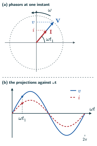
- A phasor rotates anticlockwise about the origin at angular speed ω. The length of the voltage phasor V is the peak voltage vm, and of the current phasor I the peak current im (NCERT page 181, Figure 7.4).
- Their projections on the vertical axis, vm sin ωt and im sin ωt, are the values of the voltage and current at that instant. As the phasors rotate, these projections trace out the curves of v and i against ωt (NCERT page 181, Figure 7.4(b)).
- For a resistor, V and I point in the same direction at all times: the phase angle between voltage and current is zero (NCERT page 181).
- Phasors are not vectors in space. Voltage and current are scalars. NCERT explains that the amplitudes and phases of sinusoidally varying scalars combine in the same way as the projections of rotating vectors, so phasors give a simple way to add them using a rule we already know (NCERT footnote, page 181).
Reading phase from a phasor diagram
- The angle between two phasors is the phase difference between the quantities. Since phasors rotate anticlockwise, a phasor that is behind another in the rotation lags it (reasoned from NCERT page 181).
- For an inductor, the current phasor is π/2 behind the voltage phasor: the current lags the voltage by a quarter cycle (NCERT Section 7.4, page 182). For a capacitor, the current phasor is π/2 ahead: the current leads (NCERT Section 7.5, pages 184–185).
- If the current phasor is an angle φ ahead of the voltage phasor, then v = vm sin ωt and i = im sin(ωt + φ); if it is behind, φ is negative (reasoned).
- A cosine is a sine a quarter turn ahead: im cos ωt = im sin(ωt + π/2), so its phasor is π/2 ahead (NCERT uses this step in Section 7.5, page 184).
- Adding two sinusoidal quantities of the same frequency is done by adding their phasors like vectors: the resultant phasor’s length is the amplitude of the sum, and its angle gives its phase. NCERT uses this for the series LCR circuit (NCERT Section 7.6, page 187).
Sum of two phasors φ apart (reasoned)
- Phasors are often drawn with rms lengths instead of peak lengths. Dividing every length by √2 changes no angle, so rms meter readings add as phasors too: 30 V across a resistor and 40 V across an inductor in series give √(302 + 402) = 50 V across the source, not 70 V (reasoned; NCERT Section 7.6, page 187).
Solved examples
Example 1: Reading a resistor’s phasors
A 50 Ω resistor is joined to a source of peak voltage 200 V. Give the lengths of the phasors, and the values of v and i when the phasors make 30° with the horizontal axis.
Answer: V has length vm = 200 V and I has length im = 200/50 = 4.0 A, both pointing the same way. At 30°: v = 200 sin 30° = 100 V and i = 4.0 sin 30° = 2.0 A (NCERT page 181).
Example 2: Which one lags?
The current phasor in a circuit is drawn 30° clockwise from the voltage phasor. Write v and i if v = vm sin ωt.
Answer: the phasors rotate anticlockwise, so a phasor 30° clockwise from V is behind it: the current lags by π/6. So i = im sin(ωt − π/6) (reasoned from NCERT page 181).
Example 3: Adding two voltages
Two voltages of the same frequency, v1 = 3 sin ωt and v2 = 4 sin(ωt + π/2) (in volts), act in series. Find the amplitude and phase of their sum.
Answer: the phasors are at right angles, so the resultant has length √(32 + 42) = 5 V, at an angle φ with tan φ = 4/3, φ ≈ 53° ahead of v1. So v = 5 sin(ωt + 53°) (reasoned with the phasor rule, NCERT page 181 footnote).
Example 4: An inductor’s phasors
For an inductor the current phasor is π/2 behind the voltage phasor. At the instant the voltage phasor points straight up, what are v and i?
Answer: V is vertical, so v = +vm, its peak. I is a quarter turn behind, so it lies along the horizontal axis and i = 0 at that instant (NCERT pages 182–183).
Common mistakes to avoid
Common mistake
Treating phasors as vectors in space
Voltage and current are scalars. Phasors are a bookkeeping device whose projections and additions follow the rules of rotating vectors (NCERT footnote, page 181).
Common mistake
Reading the length of a phasor as the instantaneous value
The length is the peak value; the instantaneous value is the projection on the vertical axis (NCERT page 181).
Common mistake
Getting lead and lag backwards
Phasors turn anticlockwise. The one ahead in that sense leads; the one behind lags (reasoned from NCERT page 181).
Quick revision summary
- A phasor is a vector rotating anticlockwise at angular speed ω; its length is the peak value of an ac quantity.
- The projection of a phasor on the vertical axis gives the instantaneous value, such as v = vm sin ωt.
- The angle between two phasors is the phase difference; for a resistor, V and I point the same way.
- Current lags voltage by π/2 in an inductor and leads it by π/2 in a capacitor.
- Sinusoids of the same frequency add like their phasors; voltage and current themselves are scalars.
Formula sheet
- v = vm sin ωt, i = im sin(ωt + φ)
- sum of two phasors: A2 = A12 + A22 + 2A1A2 cos φ
- phase difference = angle between phasors
Questions students ask
What is the difference between a phasor and a vector?
A vector stands for a quantity with a direction in space, such as a force, while a phasor is an arrow in a diagram standing for a quantity that varies sinusoidally in time, such as an ac voltage: its length is the amplitude, its angle from the horizontal axis is the phase ωt + φ, and its rotation at ω is simply time passing (NCERT page 181 and its footnote). So the angle between two phasors is a phase difference, not an angle in space, and turning the entire diagram preserves relative phases but advances the represented time. At a fixed clock time the instantaneous values do change; alternatively, a common phase shift can represent a new choice of time origin. What phasors take from vectors is the rule of addition, which works for quantities of one frequency and the same physical kind: voltages add to voltages, currents to currents.
Why can two phasors be added like vectors?
Two phasors can be added like vectors because the vertical projection of a vector sum is the sum of the projections, so at every instant the resultant’s projection is v1 + v2; and if both quantities have the same ω, the phasors keep a fixed angle and the parallelogram turns rigidly, so the resultant is a phasor of fixed length, a sinusoid of that frequency (reasoned from NCERT page 181 and its footnote). With different frequencies the angle between the phasors keeps changing, the resultant’s length rises and falls, and the sum is not a sinusoid. So one phasor diagram holds only quantities of one frequency, such as the voltages round a circuit driven by one source.
Why do phasors rotate anticlockwise?
Phasors rotate anticlockwise by convention, the one trigonometry uses for positive angles from the +x-axis, so a phasor turning at ω makes the angle ωt + φ and its vertical projection is A sin(ωt + φ) (NCERT pages 182 and 185, where the phasors turn counter-clockwise). Nothing physical depends on the choice, but it must be kept throughout: with the sense reversed, a phasor that leads would appear to be behind, and every lead would be read as a lag. NCERT’s reference circle for SHM turns the same way (NCERT Class 11 Physics Part II, page 264); the clockwise case is worked under clockwise motion.
How do you find the phase difference between voltage and current from the time between their peaks?
The phase difference between voltage and current is the time between matching points of the two waves as a fraction of the period, times 2π: φ = 2πΔt/T = ωΔt in radians, or 360° × Δt/T (reasoned from ω = 2π/T; NCERT page 183 uses it for the quarter-period lag in an inductor; see phase in SHM). On 50 Hz mains, with T = 20 ms, a current that peaks 4.0 ms after the voltage lags it by 360° × 4.0/20 = 72°, about 1.26 rad. The wave that peaks first leads; if the gap is more than half a period, it is simpler to say that the other wave leads by T − Δt.
How is a phasor diagram related to the reference circle of SHM?
A phasor diagram is the reference circle of simple harmonic motion applied to ac: in both, an arrow as long as the amplitude turns anticlockwise at ω, and its projection on a fixed line gives the oscillating quantity at each instant (NCERT Class 11 Physics Part II, pages 264–265; NCERT page 181). Class 11 projects on the x-axis, x = A cos(ωt + φ), and NCERT’s phasors on the vertical axis, v = vm sin ωt; either diameter works. A phasor diagram adds several arrows of one frequency to one picture, such as a voltage and a current, so their phase difference is read as an angle.
Is the phasor diagram in the JEE Main and NEET syllabus?
The phasor diagram is not named in either syllabus, but both list the topics that NCERT solves with it: Unit 14 of the JEE Main syllabus has “reactance and impedance, LCR series circuit, resonance, power in AC circuits”, and Unit 14 of the NEET (UG) 2026 syllabus has “reactance and impedance: LCR series circuit, resonance: power in AC circuits”. NCERT introduces phasors in Section 7.3 (page 181) and finds the current, impedance and phase angle of the series LCR circuit from a phasor diagram in Section 7.6 (pages 186–188), so the phasor diagram is the standard tool for those topics in both exams.
Practice questions
Try each question first, then open the answer to check your working.
-
Q1. What does the vertical projection of a voltage phasor represent?
Show answerHide answer
The value of the voltage at that instant, v = vm sin ωt (NCERT page 181).
-
Q2. What is the angle between the voltage and current phasors for a pure resistor?
Show answerHide answer
Zero: they point in the same direction at all times (NCERT page 181).
-
Q3. Two sinusoidal currents of the same frequency have amplitudes 6 A and 8 A and are 90° out of phase. What is the amplitude of their sum?
Show answerHide answer
√(62 + 82) = 10 A (reasoned with the phasor rule, NCERT page 181).