Power in ac circuits and the power factor
NCERT Class 12 Physics Chapter 7 Section 7.7
Quick answer
The average power for sinusoidal voltage and current is P = VI cos φ, where V and I are rms values and φ is the phase angle between voltage and current; cos φ is the power factor. It is 1 for a pure resistor and 0 for a pure inductor or capacitor, whose current is called wattless because it takes no average power. In a series LCR circuit cos φ = R/Z and power is dissipated only in the resistor, most of all at resonance for fixed source voltage and positive R.
With your textbook
NCERT Physics Part I (Class 12), Chapter 7 “Alternating Current”, Section 7.7 “Power in AC Circuit: The Power Factor”, pages 190–193.
Open the official NCERT chapter (PDF, 2.4 MB, ncert.nic.in) (opens in a new tab)
Checked against the 2026-27 reprint on .
What is the power factor?
Power in an ac circuit and the power factor
When sinusoidal current in an ac circuit is out of phase with the voltage, by an angle φ, the average power is less than VI: it is VI cos φ (NCERT Section 7.7, page 191). NCERT puts it this way:
So, the average power dissipated depends not only on the voltage and current but also on the cosine of the phase angle φ between them.
NCERT Physics Part I (Class 12), Section 7.7, page 191
The quantity cos φ is the power factor. It is 1 for a pure resistor and 0 for a pure inductor or capacitor, whose current is then called wattless (NCERT page 191).
In plain words: a current that is out of step with the voltage spends part of each cycle pushing energy back to the source. Only the part of the current that is in step with the voltage does lasting work. The power factor says what fraction that is.
Scope: voltage and current are sinusoidal at one frequency; R, L and C are ideal linear elements. In general, including distorted waveforms, power factor is P/(VI) and need not equal cos φ. Resonance gives maximum power here for fixed source voltage and fixed positive R. Wattless current exchanges energy during a cycle but transfers no net energy over a complete cycle.
Average power and the power factor
- In a series LCR circuit, v = vm sin ωt drives i = im sin(ωt + φ), with im = vm/Z and tan φ = (XC − XL)/R (NCERT page 190).
- The instantaneous power is p = vi, the product of vm sin ωt and im sin(ωt + φ) (NCERT Eq. (7.29), page 191). Using 2 sin A sin B = cos(A − B) − cos(A + B), it is a steady part, (vmim/2) cos φ, minus a part that oscillates at 2ω, (vmim/2) cos(2ωt + φ). The oscillating part averages to zero over a cycle (NCERT page 191).
- So the average power is (NCERT Eq. [7.30(a)], page 191):
Average power (NCERT Eq. 7.30a)
- with V and I the rms values. Since V = IZ, this is also P = I2Z cos φ (NCERT Eq. [7.30(b)], page 191).
- Case (i), a resistor alone: φ = 0, cos φ = 1, the most power for a given V and I (NCERT page 191). Case (ii), a pure inductor or capacitor, and Case (iv), resonance, follow in the next two sections.
- Case (iii), an LCR circuit: φ may be non-zero in an RL, RC or LCR circuit. Even then, power is dissipated only in the resistor (NCERT page 191). From the impedance triangle, cos φ = R/Z, so VI cos φ = I2R (reasoned; NCERT page 191).
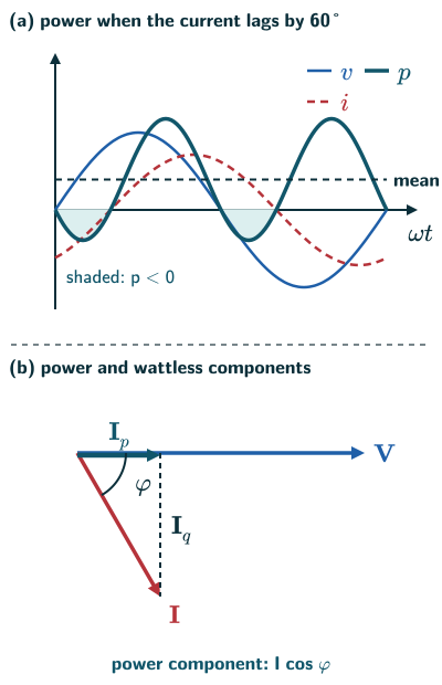
Wattless current
- Case (ii), an inductor or capacitor alone: the phase difference is π/2, so cos φ = 0 and no power is dissipated, even though a current flows. Such a current is called a wattless current (NCERT page 191).
- In general, split the current phasor into Ip = I cos φ along the voltage, the power component, and |Iq| = I |sin φ| at right angles to it, the wattless component, which carries no average power (from NCERT Figure 7.15, Example 7.7, page 192).
- Why power companies care (NCERT Example 7.7): to supply a given power at a given voltage, a small cos φ needs a large current, and the I2R loss in the transmission lines grows with it. The power factor of a lagging (inductive) load can be improved by joining a capacitor of suitable value in parallel: its leading wattless current cancels the load’s lagging one, so the current approaches the power component alone (NCERT pages 191–192).
Power at resonance
- Case (iv), resonance in an LCR circuit: XC − XL = 0, so φ = 0 and cos φ = 1, and P = I2Z = I2R. The most power is dissipated, through R, at resonance (NCERT page 191).
- NCERT’s Examples 7.8 and 7.9 show this: the same circuit dissipates 4800 W at 50 Hz but about 13.35 kW at its resonant frequency (NCERT pages 192–193).
- NCERT slip: in Example 7.9 (page 193), ω0 is found as 222.1 rad/s, but the next line divides 221.1 by 2 × 3.14. The answer printed, 35.4 Hz, follows from 222.1 rad/s; 221.1 is a misprint.
Solved examples
Example 1: Impedance, phase and power (NCERT Example 7.8)
A sinusoidal voltage of peak 283 V and frequency 50 Hz is applied to a series LCR circuit with R = 3 Ω, L = 25.48 mH and C = 796 µF. Find (a) the impedance, (b) the phase difference, (c) the power dissipated, (d) the power factor.
Answer: XL = 2π × 50 × 25.48 × 10−3 ≈ 8 Ω and XC = 1/(2π × 50 × 796 × 10−6) ≈ 4 Ω. (a) Z = √(32 + (8 − 4)2) = 5 Ω. (b) tan φ = (4 − 8)/3, so φ ≈ −53.1°: the current lags. (c) I = (283/√2)/5 ≈ 40 A, so P = I2R = 402 × 3 = 4800 W. (d) cos φ = cos(−53.1°) = 0.6 (NCERT pages 192–193).
Example 2: The same circuit at resonance (NCERT Example 7.9)
If the source frequency in Example 1 can be varied, at what frequency does resonance occur, and what are the impedance, current and power then?
Answer: LC = 25.48 × 10−3 × 796 × 10−6 ≈ 2.03 × 10⁻⁵ s2, so ω0 = 1/√(LC) ≈ 222 rad/s, so νr = 222/2π ≈ 35.3 Hz (NCERT, with π = 3.14, gets 35.4 Hz). At resonance Z = R = 3 Ω, I = (283/√2)/3 ≈ 66.7 A and P = 66.72 × 3 ≈ 13.35 kW, more than at 50 Hz (NCERT page 193).
Example 3: Power from the power factor
A motor draws 5.0 A from a 220 V supply at a power factor of 0.80. Find the average power and the power and wattless components of the current.
Answer: P = VI cos φ = 220 × 5.0 × 0.80 = 880 W. Ip = 5.0 × 0.80 = 4.0 A; |sin φ| = 0.60, so Iq = 3.0 A (NCERT Eq. [7.30(a)], page 191; Example 7.7, page 192).
Example 4: Why a low power factor costs more (based on NCERT Example 7.7)
A factory load in an ideal single-phase model needs 10 kW at 400 V. Compare the line current at power factors of 1.0 and 0.5.
Answer: I = P/(V cos φ): 10 000/400 = 25 A at cos φ = 1, but 50 A at cos φ = 0.5. Twice the current means four times the I2R loss in the same lines (reasoned from NCERT Example 7.7, pages 191–192).
Common mistakes to avoid
Common mistake
Using VI as the power of an ac circuit
The average power is VI cos φ. VI alone is the most it could be, reached only when the current is in phase with the voltage (NCERT page 191).
Common mistake
Thinking an inductor or capacitor dissipates power
In an LCR circuit power is dissipated only in the resistor; a pure inductor or capacitor takes a wattless current (NCERT page 191).
Common mistake
Using peak values in P = VI cos φ
V and I in VI cos φ are rms values. With peak values the power is vmim cos φ/2 (NCERT Eq. [7.30(a)], page 191).
Quick revision summary
- Average power in an ac circuit: P = VI cos φ = I2Z cos φ, with V and I rms values; cos φ is the power factor.
- Resistor: cos φ = 1, most power. Pure inductor or capacitor: cos φ = 0, wattless current, no average power.
- In an LCR circuit, cos φ = R/Z and the power, I2R, is dissipated only in the resistor.
- At resonance φ = 0 and the power is greatest; a low power factor raises line losses, and a capacitor in parallel can improve it.
Formula sheet
- P = VI cos φ = I2 Z cos φ
- power factor: cos φ = R/Z
- power component: I cos φ
- wattless component magnitude: I |sin φ|
- at resonance: P = I2 R
Questions students ask
What is the difference between apparent power, true power and reactive power?
In an ac circuit the true (real) power is the average power used, P = VI cos φ, in watts (NCERT Eq. [7.30(a)], page 191). Beyond the NCERT text, the apparent power S = VI is in volt-amperes (VA), and reactive power has magnitude |Q| = VI |sin φ|, in volt-amperes reactive (var). It measures the quadrature component’s reversible energy exchange, not the amplitude of the entire instantaneous-power oscillation (that amplitude is S). With NCERT’s φ = current phase minus voltage phase, the conventional signed reactive power is Q = −VI sin φ: positive for an inductive load, negative for a capacitive load. The magnitudes form a right triangle, with cos φ = P/S (US DOE Fundamentals Handbook: Electrical Science, 1992, Module 9). So a load drawing 2.5 A from 230 V at a power factor of 0.96 has S = 575 VA, P = 552 W and |Q| = 161 var; the sign requires knowing whether the load is inductive or capacitive.
What do leading and lagging power factor mean?
A lagging power factor means the current lags behind the voltage, as in an inductive circuit, and a leading one means the current is ahead of it, as in a capacitive circuit (beyond the NCERT text, the names: US DOE Fundamentals Handbook: Electrical Science, 1992, Module 9); NCERT’s φ is then negative or positive (NCERT page 188). The label is needed because cos φ is the same for +φ and −φ: a power factor of 0.87 could belong to a current 30° ahead of the voltage or 30° behind it. A unity power factor, cos φ = 1, is neither: the current is in phase with the voltage, as with a pure resistance or a series LCR circuit at resonance (NCERT page 191).
Can the power factor be negative or greater than 1?
For a passive RLC circuit in periodic steady state, with a well-defined nonzero rms current and voltage, the power factor lies between 0 and 1: for a series circuit it is cos φ = R/Z, and Z = √(R + (XC − XL)2) is never smaller than R (NCERT pages 187 and 191), which fits NCERT’s remark that the power consumed in an ac circuit is never negative (Points to Ponder 3, page 198). It is 1 only when φ = 0, and, for a series circuit with nonzero Z, 0 when R = 0, as for a pure inductor or capacitor. The ideal R = 0 circuit at resonance has Z = 0 and no finite driven steady state. Beyond the NCERT text, a negative cos φ would mean average power flowing back to the supply, which only a source can deliver, such as a generator or rooftop solar panels feeding the grid (reasoned from P = VI cos φ).
What is the difference between power factor and efficiency?
Power factor and efficiency are both fractions, of different things: the power factor cos φ = P/(VI) is the share of VI that is real power (NCERT Eq. [7.30(a)], page 191), while the efficiency is the share of that real power that becomes useful output, such as a motor’s mechanical power (NCERT pages 195 and 199). A low power factor wastes no energy in itself, as the wattless current takes no average power, but it adds to the current and so to the IR loss in the wires (NCERT Example 7.7, pages 191–192). So a motor drawing 6.0 A from 230 V at a power factor of 0.75 takes 1035 W of its 1380 VA, and with 0.90 kW of mechanical output it is 87% efficient.
How do you find the capacitor needed to correct a power factor to 1?
To raise a lagging power factor to 1, choose a capacitor in parallel whose current, VωC, equals the load’s wattless component I |sin φ|, so that the two cancel and the supply carries only the power component I cos φ (NCERT Example 7.7, pages 191–192; capacitive reactance XC = 1/ωC, NCERT page 184). That gives C = I |sin φ|/(ωV). For a 1.5 kW load on 230 V, 50 Hz at a power factor of 0.70, I = 1500/(230 × 0.70) ≈ 9.32 A and I |sin φ| ≈ 6.65 A, so C ≈ 6.65/(314 × 230) F ≈ 92 µF, and the supply current falls to 1500/230 ≈ 6.52 A.
Practice questions
Try each question first, then open the answer to check your working.
-
Q1. What is the power factor of a purely resistive circuit, and of a purely inductive one?
Show answerHide answer
1 and 0 (NCERT page 191).
-
Q2. A circuit draws 2.0 A rms at 230 V rms with a phase difference of 60°. Find the average power.
Show answerHide answer
P = VI cos φ = 230 × 2.0 × 0.5 = 230 W (NCERT Eq. [7.30(a)], page 191).
-
Q3. What is a wattless current?
Show answerHide answer
A current that flows without any average power being dissipated, as in a purely inductive or capacitive circuit, where cos φ = 0 (NCERT page 191).