AC voltage applied to a capacitor
NCERT Class 12 Physics Chapter 7 Section 7.5
Quick answer
When a sinusoidal voltage v = vm sin ωt is applied to an ideal linear capacitor, the current is i = im sin(ωt + π/2): it leads the voltage by π/2, a quarter cycle. Its amplitude is im = vm/XC, where the capacitive reactance XC = 1/(ωC) = 1/(2πνC) falls as the frequency rises and is infinite for steady dc, which a capacitor therefore blocks. The average power supplied to the capacitor over a cycle is zero.
With your textbook
NCERT Physics Part I (Class 12), Chapter 7 “Alternating Current”, Section 7.5 “AC Voltage Applied to a Capacitor”, pages 184–186.
Open the official NCERT chapter (PDF, 2.4 MB, ncert.nic.in) (opens in a new tab)
Checked against the 2026-27 reprint on .
What happens when an ac voltage is applied to a capacitor?
AC voltage applied to a capacitor
An ac source v = vm sin ωt is joined to a capacitor alone: a purely capacitive circuit (NCERT Section 7.5, page 184). In a dc circuit a capacitor stops the current once it is charged, but with ac it is charged and discharged every half cycle, so a current keeps flowing. Its size is set by the capacitive reactance XC = 1/(ωC):
The capacitive reactance limits the amplitude of the current in a purely capacitive circuit in the same way as the resistance limits the current in a purely resistive circuit.
NCERT Physics Part I (Class 12), Section 7.5, page 185
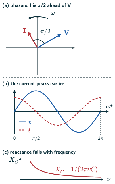
The current is a quarter cycle ahead of the voltage, and the average power over a cycle is zero (NCERT page 185).
In plain words: no charge actually crosses the gap between the plates, but charge flows back and forth in the wires as the capacitor fills and empties. The current is largest when the voltage is changing fastest, which is a quarter cycle before the voltage peaks. The faster the voltage alternates, the more charge sloshes per second, so a capacitor lets high frequencies through more easily.
Model used throughout: an ideal, lossless, linear capacitor of constant C. The sinusoidal formulas describe operation below frequencies where stray inductance and other real-component effects matter.
Current leads the voltage by π/2
- At any instant the voltage across the capacitor is v = q/C (NCERT Eq. (7.15), page 184), and by Kirchhoff’s loop rule it equals the source voltage, so q = Cvm sin ωt.
- The current is i = dq/dt = ωCvm cos ωt. Using cos ωt = sin(ωt + π/2) (NCERT Eq. (7.16), page 184):
Current in a capacitor (NCERT Eq. 7.16)
- So the current leads the voltage by π/2. In the phasor diagram the current phasor I is π/2 ahead of the voltage phasor V as they rotate anticlockwise, and the current reaches its maximum a quarter period earlier than the voltage (NCERT page 185, Figure 7.8).
Capacitive reactance
- The current amplitude is im = ωCvm = vm/(1/(ωC)). The quantity 1/(ωC) plays the part of a resistance and is called the capacitive reactance (NCERT Eqs. (7.17)–(7.18), page 184):
Capacitive reactance (NCERT Eq. 7.17)
- With it, im = vm/XC; dividing both amplitudes by √2, the rms values obey I = V/XC too (as in NCERT Example 7.4). XC has the dimensions of resistance and its SI unit is the ohm, but it is inversely proportional to the frequency and to the capacitance (NCERT page 185).
- For steady dc (ν = 0), XC is infinite: a charged capacitor blocks dc (reasoned from NCERT Eq. (7.17), agreeing with NCERT Example 7.3).
Zero average power in a capacitor
- The instantaneous power supplied to the capacitor is pC = iv = imvm cos ωt sin ωt = (imvm/2) sin 2ωt (NCERT Eq. (7.19), page 185).
- Since sin 2ωt averages to zero over a cycle, the average power supplied to a capacitor is zero, as for an inductor (NCERT page 185).
- So a current flows but no power is used up on average. NCERT calls the current in a purely inductive or capacitive circuit a wattless current (NCERT Section 7.7, page 191).
- In one quarter cycle the capacitor stores energy in its electric field; in the next it returns it to the source (reasoned from the sign of pC).
- NCERT sums up: in an inductor the current lags the voltage by π/2, and in a capacitor it leads by π/2 (NCERT page 185).
Solved examples
Example 1: A lamp and a capacitor (NCERT Example 7.3)
A lamp is connected in series with a capacitor. What happens with a dc source and with an ac source, and what changes if the capacitance is reduced?
Answer: with dc, the capacitor charges and then no current flows, so there is no sustained glow; a brief charging flash is possible. With ac, the capacitor offers a reactance 1/(ωC) and a current flows, so the lamp can glow if that current is sufficient. Reducing C increases the reactance, so the lamp glows less brightly (NCERT page 185).
Example 2: Reactance and current (NCERT Example 7.4)
A 15.0 µF capacitor is connected to a 220 V, 50 Hz source. Find the capacitive reactance, the rms and peak currents, and what happens if the frequency is doubled.
Answer: XC = 1/(2π × 50 × 15.0 × 10−6) ≈ 212 Ω. I = 220/212 ≈ 1.04 A, and im = √2 × 1.04 ≈ 1.47 A, ahead of the voltage by π/2. Doubling the frequency halves XC and so doubles the current (NCERT pages 185–186).
Example 3: Choosing a frequency
At what frequency does a 10 µF capacitor have a reactance of 100 Ω?
Answer: ν = 1/(2πXCC) = 1/(2π × 100 × 10 × 10−6) ≈ 159 Hz (NCERT Eq. (7.17), page 184).
Example 4: An instant in the cycle
A 20 µF capacitor is joined to v = 200 sin(100πt) V. Find the current amplitude and the current at the instant the voltage is zero and rising.
Answer: XC = 1/(100π × 20 × 10−6) ≈ 159 Ω, so im = 200/159 ≈ 1.26 A. When the voltage is zero and rising, ωt = 0 and i = im sin(π/2) = +1.26 A, its peak (NCERT Eqs. (7.16)–(7.18), page 184).
Common mistakes to avoid
Common mistake
Thinking no current flows through a capacitor in an ac circuit
No charge crosses the gap, but the capacitor is charged and discharged every half cycle, so a current flows in the circuit (NCERT page 184).
Common mistake
Expecting the reactance to rise with frequency
XC = 1/(2πνC) falls as the frequency rises; it is XL that rises (NCERT pages 182 and 185).
Common mistake
Mixing up lead and lag
In a capacitor the current leads the voltage by π/2; in an inductor it lags (NCERT page 185).
Quick revision summary
- In a purely capacitive circuit, v = vm sin ωt gives i = im sin(ωt + π/2): the current leads the voltage by π/2.
- Capacitive reactance XC = 1/(ωC) = 1/(2πνC), in ohm; im = vm/XC.
- XC falls as the frequency or the capacitance rises; a capacitor blocks steady dc.
- The average power supplied to a capacitor over a cycle is zero: the current is wattless.
Formula sheet
- v = vm sin ωt, i = im sin(ωt + π/2)
- XC = 1/(ωC) = 1/(2πνC)
- im = vm/XC
- average power: PC = 0
Questions students ask
Why does a capacitor block DC but allow AC?
A capacitor blocks a steady direct current because its plates charge towards the supply voltage and the transient current dies away on a timescale set by the circuit resistance and capacitance, but it allows an alternating current because a voltage that keeps reversing keeps charging and discharging the plates, so charge flows to and fro in the wires (NCERT page 184). No charge crosses the gap in either case: the changing field between the plates, the displacement current of NCERT Chapter 8, links the currents on the two sides. Thus a series capacitor blocks the steady component and can couple the alternating component, with attenuation depending on frequency and the rest of the circuit (beyond the NCERT text: US Navy, NEETS Module 2, 1998, page 4-8).
What is the difference between inductive reactance and capacitive reactance?
Inductive reactance XL = ωL rises in proportion to the frequency and comes with a current lagging the voltage by π/2, while capacitive reactance XC = 1/(ωC) falls as the frequency rises and comes with a current leading by π/2; both are in ohm, and neither takes net energy over a cycle (NCERT pages 182–185). So they are opposite at the extremes: for steady dc a coil has no reactance and a capacitor an infinite one, and their ideal reactances approach the opposite limits as frequency rises. Real components cease to follow these simple models when parasitic effects matter. In series their effects oppose each other and cancel fully at resonance, where XL = XC.
Is capacitive reactance negative, and why do some books give it a minus sign?
No, capacitive reactance as NCERT defines it, XC = 1/(ωC), is positive, in ohm, like XL = ωL (NCERT page 184). Some books give it a minus sign for its opposite effect on phase: impedance diagrams draw XL along +90° and XC along −90°, so they subtract to a net reactance X = XL − XC (beyond the NCERT text: US Department of Energy, DOE Fundamentals Handbook: Electrical Science, 1992, Module 8). NCERT uses XC − XL in the impedance and tan φ (NCERT pages 187–188); its sign shows whether a circuit is capacitive or inductive.
Why is capacitive reactance measured in ohms, and what is its dimensional formula?
Capacitive reactance is measured in ohms because it is the ratio of the voltage amplitude to the current amplitude, XC = vm/im, a volt per ampere, just as a resistance is, and its dimensional formula is that of resistance, [M L T A] (NCERT pages 184–185 and the table on page 198). The units of XC = 1/(ωC) agree: ω is in s and the farad is C V = A s V (NCERT Chapter 2, page 68), so 1/(s × A s V) = V A = Ω. Unlike an ohm of resistance, though, an ohm of reactance turns no energy into heat over a cycle (NCERT page 185).
What is the difference between capacitance and capacitive reactance?
Capacitance C = Q/V is a property of the capacitor itself, fixed by its plates, their separation and the dielectric and measured in farad, while capacitive reactance XC = 1/(ωC) is its opposition to an alternating current of a given frequency, measured in ohm (NCERT Chapter 2, pages 67–68; NCERT page 184). The two vary inversely: a larger capacitance takes more charge each half cycle (q = Cv), so it passes more current and has less reactance; a 22 µF capacitor has XC ≈ 145 Ω at 50 Hz but about 7.2 Ω at 1.0 kHz. Capacitance means something in dc circuits too, while reactance belongs only to sinusoidal ac.
Practice questions
Try each question first, then open the answer to check your working.
-
Q1. In a purely capacitive circuit, does the current lead or lag the voltage, and by how much?
Show answerHide answer
It leads by π/2 (NCERT page 185).
-
Q2. Find the reactance of a 5.0 µF capacitor at 50 Hz.
Show answerHide answer
XC = 1/(2π × 50 × 5.0 × 10−6) ≈ 637 Ω (NCERT Eq. (7.17), page 184).
-
Q3. Why does a lamp in series with a capacitor not glow on a dc supply?
Show answerHide answer
Once the capacitor is charged, no current flows in a dc circuit (NCERT Example 7.3, page 185).