Series LCR circuit
NCERT Class 12 Physics Chapter 7 Section 7.6
Quick answer
In an ideal series LCR circuit with R > 0 in sinusoidal steady state the same current flows through R, L and C, and their voltages add as phasors: VR is in phase with the current, VL is π/2 ahead and VC is π/2 behind. This gives the impedance Z = √(R2 + (XC − XL)2), the current amplitude im = vm/Z and the phase angle tan φ = (XC − XL)/R. At resonance XL = XC, so ω0 = 1/√(LC), Z = R and the current is largest for fixed source amplitude, which is how a radio is tuned.
With your textbook
NCERT Physics Part I (Class 12), Chapter 7 “Alternating Current”, Section 7.6 “AC Voltage Applied to a Series LCR Circuit”, pages 186–190.
Open the official NCERT chapter (PDF, 2.4 MB, ncert.nic.in) (opens in a new tab)
Checked against the 2026-27 reprint on .
What is a series LCR circuit?
Series LCR circuit
A resistor R, an inductor L and a capacitor C are joined in series to an ac source v = vm sin ωt (NCERT Section 7.6, page 186, Figure 7.10). The same current flows through all three, but the voltages across them are out of phase, so they add as phasors. The circuit’s opposition to the current is its impedance Z, and the current is largest at one frequency, the resonant frequency. NCERT adds:
It is important to note that resonance phenomenon is exhibited by a circuit only if both L and C are present in the circuit.
NCERT Physics Part I (Class 12), Section 7.6.2, page 189
In plain words: the inductor’s voltage is a quarter cycle ahead of the current, the capacitor’s a quarter cycle behind, so the two work against each other. What is left of their difference combines with the resistor’s voltage like the two sides of a right triangle. At one special frequency the inductor and capacitor cancel exactly, and only the resistor holds the current back.
Model used throughout: constant, ideal L and C, a positive constant resistance R, and sinusoidal steady state after transients have decayed. Z denotes the impedance magnitude. The resonance maximum assumes a source of fixed voltage amplitude as frequency varies. With R = 0, transients need not decay, and at resonance an ideal voltage source has no finite sinusoidal steady-state current.
Phasor-diagram solution
- In series, the current is the same in every element at every instant, i = im sin(ωt + φ), where φ is the phase difference between the source voltage and the current (NCERT Eq. (7.21), page 187).
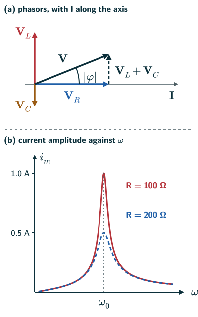
- Relative to the current phasor I: VR is parallel to I, VL is π/2 ahead and VC is π/2 behind. Their lengths are vRm = imR, vLm = imXL and vCm = imXC (NCERT Eq. (7.22), page 187).
- Kirchhoff’s loop rule gives L di/dt + iR + q/C = v (NCERT Eq. (7.20), page 186), that is, vL + vR + vC = v, so the phasors add: VL + VR + VC = V (NCERT Eqs. (7.23)–(7.24), page 187).
- VL and VC lie on one line in opposite directions, so they combine into one phasor of length |vCm − vLm|. V is the hypotenuse of a right triangle with sides VR and this combined phasor, VC + VL, so vm2 = vRm2 + (vCm − vLm)2 (NCERT page 187). This gives the current amplitude (NCERT Eq. [7.25(a)], page 187):
Current amplitude (NCERT Eq. 7.25a)
- The phase angle follows from the same triangle (NCERT Eq. (7.27), page 188):
Phase angle (NCERT Eq. 7.27)
- If XC > XL, φ is positive: the circuit is mainly capacitive and the current leads the source voltage. If XC < XL, φ is negative: the circuit is mainly inductive and the current lags (NCERT page 188).
- This is the steady-state solution: the phasor diagram says nothing about the initial condition. The general solution also has a transient part, which exists even for v = 0 and dies out after a sufficiently long time (NCERT page 188).
Impedance
- By analogy with resistance, the impedance is Z = vm/im (NCERT Eq. [7.25(b)], page 187), where (NCERT Eq. (7.26), page 187):
Impedance (NCERT Eq. 7.26)
- Z is in ohm. R, XC − XL and Z form a right triangle, the impedance diagram, with Z as its hypotenuse and φ the angle between R and Z (NCERT page 188, Figure 7.12).
- Because the voltages across R, L and C are out of phase, their rms values do not add up to the source voltage like ordinary numbers; they add as phasors (NCERT Example 7.6, page 190).
Resonance
- A system that tends to oscillate at a natural frequency responds strongly when driven near that frequency, like a child on a swing pulling the ropes in time with the swing (NCERT pages 188–189).
- As ω increases, XC = 1/ωC falls and XL = ωL rises. At the frequency where they are equal, Z is smallest, Z = R, and the current amplitude is largest, im = vm/R. This is the resonant frequency (NCERT Eq. (7.28), page 189):
Resonant frequency (NCERT Eq. 7.28)
- Below ω0, XC > XL: the circuit is capacitive and the current leads the source voltage. Above ω0, XL > XC: it is inductive and the current lags (reasoned from NCERT Eqs. (7.27)–(7.28), pages 188–189).
- NCERT’s case: L = 1.00 mH, C = 1.00 nF and vm = 100 V give ω0 = 1.00 × 10⁶ rad/s; at resonance the current amplitude is 1.0 A for R = 100 Ω and 0.5 A for R = 200 Ω, twice as much for half the resistance (NCERT page 189).
- At resonance the voltages across L and C cancel, and the whole source voltage appears across R. This cancellation needs both L and C, so there is no resonance in an RL or RC circuit (NCERT page 189).
- NCERT slip: page 189 refers to “Figure 7.16” for the graph of im against ω; the graph on that page is Figure 7.14.
Tuning a radio
- A radio’s antenna picks up signals from many stations, and they drive the tuning circuit at many frequencies. To hear one station, the capacitance in the tuning circuit is varied until the resonant frequency nearly equals that station’s frequency; the current at that frequency is then largest (NCERT page 189).
- The smaller the resistance, the higher and sharper the resonance peak, so a station is picked out more cleanly (reasoned from NCERT Figure 7.14).
- In NCERT’s simplified metal-detector model, resonance is used: you walk through a coil joined to a capacitor tuned to resonance. Metal in your pocket changes the circuit’s impedance and so the current, and the change sets off an alarm (NCERT Example 7.10, page 193).
Solved examples
Example 1: A resistor and a capacitor (NCERT Example 7.6)
A 200 Ω resistor and a 15.0 µF capacitor are joined in series to a 220 V, 50 Hz source. Find the current and the rms voltages across the resistor and the capacitor. Why does their sum exceed 220 V?
Answer: With π = 3.14, as NCERT takes it, XC = 1/(2π × 50 × 15.0 × 10−6) ≈ 212.3 Ω, so Z = √(2002 + 212.32) ≈ 291.7 Ω and I = 220/291.7 ≈ 0.754 A (NCERT divides by 291.5 and gets 0.755 A). VR = IR ≈ 151 V and VC = IXC ≈ 160 V. Their sum, about 311 V, is more than 220 V because the two voltages are 90° out of phase and must be added as phasors: √(1512 + 1602) ≈ 220 V (NCERT page 190).
Example 2: An inductive circuit
In a series circuit R = 30 Ω, XL = 80 Ω and XC = 40 Ω, with a 100 V rms source. Find Z, the current, the phase angle and the voltage across each element.
Answer: Z = √(302 + (40 − 80)2) = 50 Ω, so I = 100/50 = 2.0 A. tan φ = (40 − 80)/30, so φ ≈ −53°: the current lags. VR = 60 V, VL = 160 V and VC = 80 V; the voltage across L alone is more than the source voltage (NCERT Eqs. (7.22)–(7.27), pages 187–188).
Example 3: At resonance
A series circuit has L = 0.50 H, C = 8.0 µF and R = 20 Ω, with a 100 V rms source. Find the resonant frequency, the current at resonance and the voltage across the inductor.
Answer: ω0 = 1/√(0.50 × 8.0 × 10−6) = 500 rad/s, about 80 Hz. At resonance Z = R, so I = 100/20 = 5.0 A. VL = Iω0L = 5.0 × 500 × 0.50 = 1250 V, with an equal and opposite voltage across C (NCERT Eq. (7.28), page 189; the voltage across L is reasoned).
Example 4: A metal detector (NCERT Example 7.10)
What is the principle of the resonant metal-detector model described in NCERT?
Answer: resonance in an ac circuit in this model; actual detectors can use other induction and signal-processing methods (beyond NCERT: NIST/NIJ Guide 600-00, discussion of continuous-wave and pulsed sources). The doorway is a coil of many turns joined to a capacitor tuned to resonance. Metal carried through it changes the impedance, so the current changes noticeably, and the electronics sound an alarm (NCERT page 193).
Common mistakes to avoid
Common mistake
Adding the rms voltages across R, L and C as numbers
They are out of phase, so they add as phasors: V2 = VR2 + (VL − VC)2 (NCERT Example 7.6, page 190).
Common mistake
Getting the sign of φ backwards
With tan φ = (XC − XL)/R, a capacitive circuit has positive φ and the current leads; an inductive one has negative φ and the current lags (NCERT page 188).
Common mistake
Expecting resonance in an RC or RL circuit
Resonance needs both L and C, so that their voltages can cancel (NCERT page 189).
Quick revision summary
- In a series LCR circuit the current i = im sin(ωt + φ) is the same in every element; VR is in phase with it, VL π/2 ahead and VC π/2 behind.
- The voltages add as phasors, giving Z = √(R2 + (XC − XL)2) and im = vm/Z.
- tan φ = (XC − XL)/R: positive φ (current leads) for a capacitive circuit, negative φ (lags) for an inductive one.
- At resonance XL = XC, ω0 = 1/√(LC), Z = R and the current is largest; it needs both L and C.
- Tuning a radio means adjusting C until ω0 matches the station.
Formula sheet
- i = im sin(ωt + φ), im = vm/Z
- Z = √(R2 + (XC − XL)2)
- tan φ = (XC − XL)/R
- resonance: XL = XC, ω0 = 1/√(LC), Z = R
Questions students ask
What is the difference between impedance, resistance and reactance?
Resistance, reactance and impedance are all in ohm but are different oppositions to a current: resistance R turns electrical energy into heat, in dc and ac alike; a coil’s or a capacitor’s reactance changes with frequency and takes no average power; and the impedance Z = vm/im is the whole circuit’s opposition (NCERT pages 179–187). A reactance’s voltage is a quarter cycle out of step with R’s, so the two add like the sides of a right triangle with Z as its hypotenuse (NCERT pages 187–188). So 33 Ω of resistance in series with an ideal coil of reactance 56 Ω gives Z = √(33 + 56) = 65 Ω, not 89 Ω.
Is an LCR circuit the same as an RLC circuit, and what does LCR stand for?
Yes, an LCR circuit and an RLC circuit are the same thing, an inductor L, a capacitor C and a resistor R joined to an ac source, the letters being the symbols of their inductance, capacitance and resistance; NCERT uses both names, ‘series LCR circuit’ in the title of Section 7.6 (page 186) and ‘series RLC circuit’ on pages 188–189. In a series circuit the order in which the three are joined changes nothing: the same current flows through each, so the voltage across each element, the impedance and the phase angle are the same whichever comes first (reasoned from NCERT page 187). Both exam syllabuses call it the ‘LCR series circuit’.
Is the resonant frequency of an LCR circuit the same as its natural frequency?
It equals the undamped natural frequency: the resonant frequency ω0 = 1/√(LC) of a series LCR circuit (NCERT Eq. (7.28), page 189) is the undamped LC frequency, the name NCERT Exercise 7.7 (page 200) uses for it; ω0 does not depend on R, which only lowers and widens the current peak (NCERT Figure 7.14, page 189). Beyond the NCERT text, a charged capacitor joined to an ideal coil, as in NCERT Exercise 7.6, oscillates freely at ω0, but an underdamped resistance, R < 2√(L/C), makes the free oscillations decay at angular frequency √(1/(LC) − R/(4L)) (solving NCERT Eq. (7.20) with v = 0): for L = 1.6 H, C = 0.40 µF and R = 320 Ω, 1246 rad/s against 1250 rad/s. At or above critical damping the free response does not oscillate; current resonance under sinusoidal driving still occurs at ω in this ideal series model.
What is the quality factor Q of a series LCR circuit?
The quality factor of a series LCR circuit is Q = ω0L/R = 1/(ω0CR), a pure number NCERT gives only in its table of quantities (page 198). A small R gives a high Q and a sharp resonance peak, and at resonance the voltages across L and across C are each Q times the source voltage, as VL = (V/R)ω0L (reasoned from NCERT page 189). Beyond the NCERT text, Q = ω0/Δω, with Δω the bandwidth between the half-power points, where the current is 1/√2 of its peak (US Navy, NEETS Module 9, 1998, pages 1-29 to 1-30). So 32 mH, 1.25 µF and 3.2 Ω give ω0 = 5000 rad/s, Q = 50 and Δω = 100 rad/s.
Why is a series LCR circuit called an acceptor circuit?
A series LCR circuit is called an acceptor circuit, a name beyond the NCERT text, because at resonance its impedance is smallest, Z = R, so it accepts current at the resonant frequency more readily than at any other, as in radio tuning (NCERT page 189). An inductor and a capacitor in parallel do the reverse: at resonance their currents cancel, so the pair has its largest impedance and draws the least current, and it is called a rejector circuit (beyond the NCERT text: US DOE Fundamentals Handbook: Electrical Science, 1992, Module 8; the names appear in, for example, US patents US5200703A (acceptor) and US4255728A (rejector)). Only the series circuit is in NCERT and the syllabuses.
Is the series LCR circuit in the JEE Main and NEET syllabus, and which chapter is it in?
Yes, the series LCR circuit is in both syllabuses: Unit 14 of the JEE Main syllabus lists “reactance and impedance, LCR series circuit, resonance”, and Unit 14 of the NEET (UG) 2026 syllabus “reactance and impedance: LCR series circuit, resonance”. In NCERT it is Section 7.6 of Chapter 7, Alternating Current, in Class 12 Physics Part I (pages 186–190), with the phasor-diagram solution, impedance, resonance and Example 7.6; the power it takes is in Section 7.7 (pages 190–193). Neither syllabus names the quality factor or parallel resonance, and NCERT treats neither, apart from one line for the quality factor in its table of quantities (page 198).
Practice questions
Try each question first, then open the answer to check your working.
-
Q1. What is the impedance of a series LCR circuit at resonance?
Show answerHide answer
Z = R, its smallest value, since XL = XC (NCERT page 189).
-
Q2. A series circuit has L = 2.0 mH and C = 5.0 µF. Find its resonant angular frequency.
Show answerHide answer
ω0 = 1/√(2.0 × 10−3 × 5.0 × 10−6) = 1/√(1.0 × 10−8) = 1.0 × 10⁴ rad/s (NCERT Eq. (7.28), page 189).
-
Q3. In a series LCR circuit XC > XL. Does the current lead or lag the source voltage?
Show answerHide answer
It leads: φ is positive and the circuit is mainly capacitive (NCERT page 188).